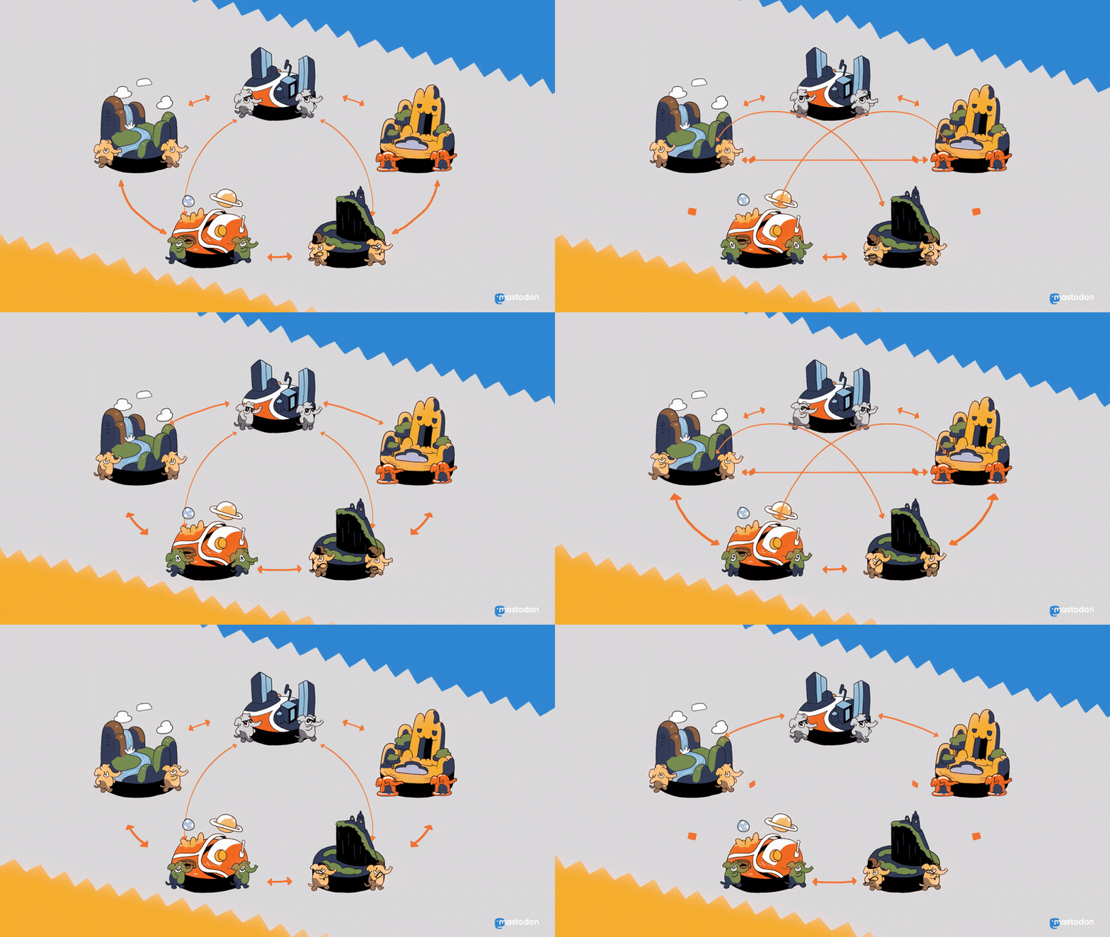
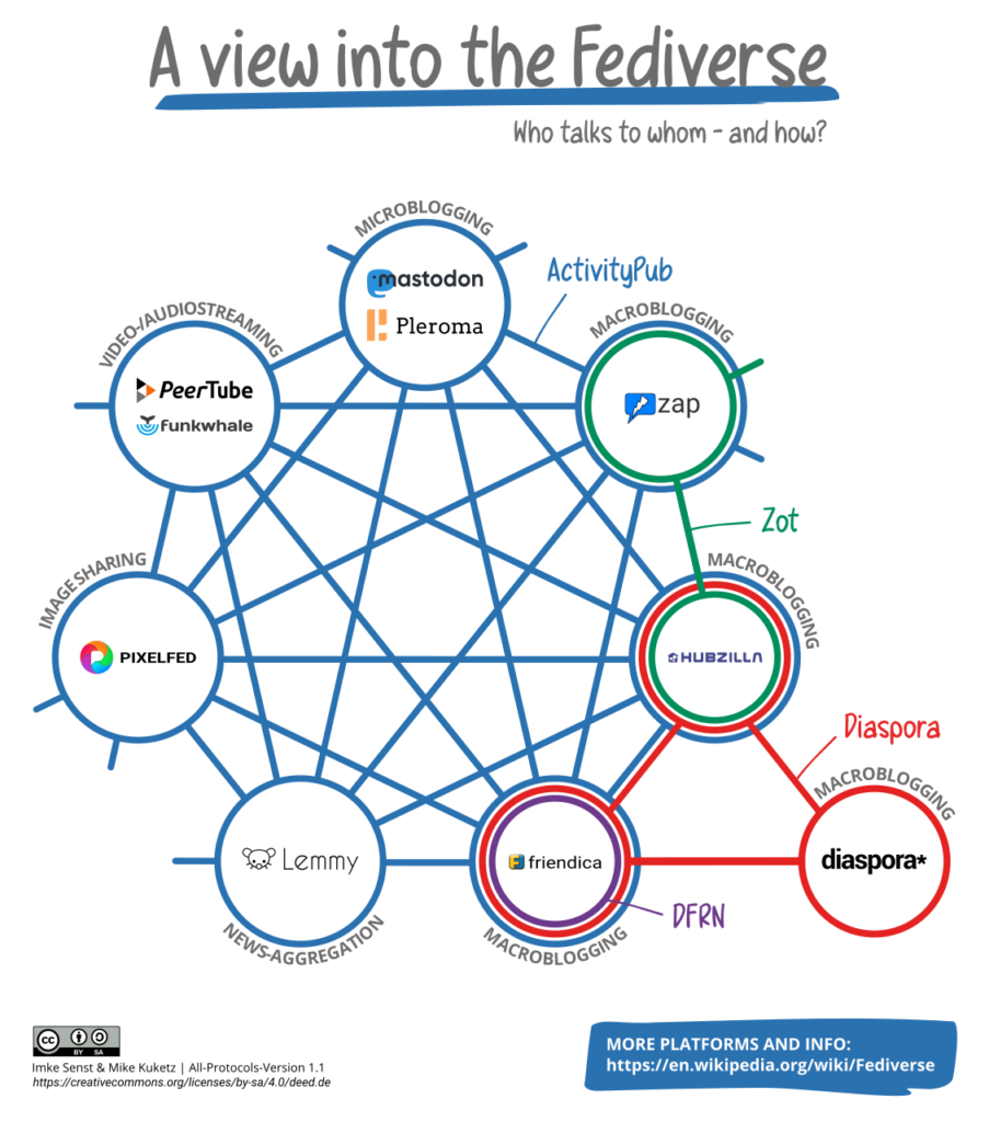
Un réseau social distribué, c’est à dire décentralisé et interopérable.
Illustrations par Eugen Rochko
Décentralisé : Chaque serveur Mastodon est
totalement indépendant, mais capable d’interagir avec les autres pour
former un réseau social mondial.
Interopérable : Basé sur des protocoles web ouverts, Mastodon peut communiquer avec n’importe quelle autre plateforme qui implémente ActivityPub. Avec un seul compte, vous avez accès à tout un univers de médias sociaux — le Fédiverse.
Chaque serveur a ses propres règles, de contenus, de modérations etc. Choisissez celui qui vous convient le mieux : https://joinmastodon.org/fr/servers
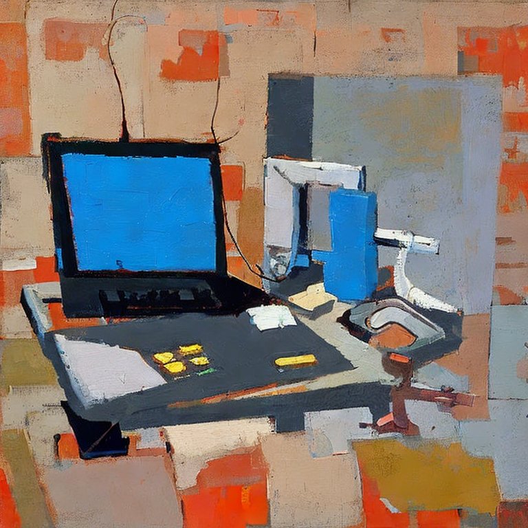
Nerd developing at home, with the style of Nicolas de Staël, courtesy of Stable Diffusion
Working with Quasar (Vue.js based) is a bliss for Web UI / SPA / etc… development. Especially is you use Vite, for the speed of site build. I highly recommend it. Now vercel makes it super easy to host and test your app online.
Here is a little problem I encountered, so I’m sharing (so that the monster Internet search engines that swallow everything can index this little helper blog post).
Contrary to what you can find in Quasar Documentation, namely here, the vercel.json file content should not be:
(My pull request to quasar to fix this was accepted and is now fixed in their doc)
Basically it’s because you don’t know that it’s gonna be an index.html handling the traffic: it’s not. It’s the application residing at / that handles everything.
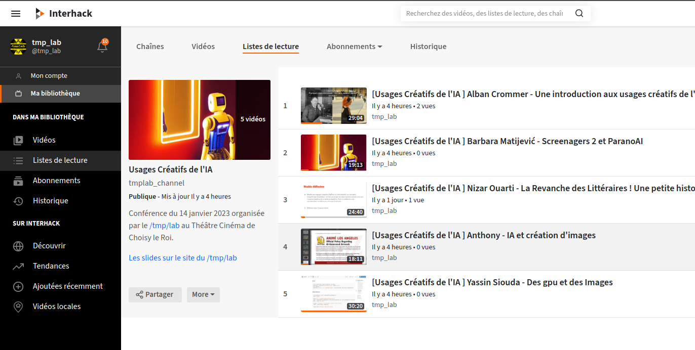
Suite à cette conférence, nous publions les vidéos et les slides des présentateurs et présentatrices qui nous ont fait l’honneur d’y présenter leur travail.
Vous voulez en savoir plus sur les nouvelles IA qui défraient la chronique, que ce soit ChatGPT ou Stable Diffusion ? Cette conférence est faite pour vous.
Des hackers, des chercheurs, des artistes, réuni.e.s pour s’informer et discuter des enjeux de ces techniques qui commencent à infuser dans la société.
Entre histoire des techniques, analyses sociologiques, pratiques personnelles et analyses technique en profondeur, on vous invite à venir apprendre, vous faire une idée et échanger sur ce sujet en plein accélération.
QUOI
Conférence sur l’IA Générative
Machine Learning / texte, son, image
QUAND
Samedi 14 janvier 2023 de 16h à 19h
OÙ
Théâtre de Choisy-le-Roi, RER C
4, avenue de Villeneuve Saint-Georges 94600 Choisy-le-Roi
COMMENT
Entrée libre
Streaming sur streaming.tmplab.org
QUOI
Vous voulez en savoir plus sur les nouvelles IA qui défraient la chronique, que ce soit ChatGPT ou Stable Diffusion ? Cette conférence est faite pour vous.
Des hackers, des chercheurs, des artistes, réuni.e.s pour s’informer et discuter des enjeux de ces techniques qui commencent à infuser dans la société.
Entre histoire des techniques, analyses sociologiques, pratiques personnelles et analyses technique en profondeur, on vous invite à venir apprendre, vous faire une idée et échanger sur ce sujet en plein accélération.
PROGRAMME
16:00 Alban
Une introduction aux usages créatifs de l’IA générative
Panorama de la situation actuelle en texte / image / son
Histoire des innovations et des usages en IA Générative
Les enjeux sociaux – politiques – économiques – environnement
Prospective
16:30 Valentin Goujon
Des réseaux antagonistes génératifs aux modèles basés sur la diffusion : une histoire récente de l’art génératif
Description : Brève généalogie des différents types de modèles génératifs (notamment les GANs et les modèles basés sur la diffusion) afin de retracer l’essor de l’art génératif basé sur des réseaux de neurones profonds depuis le début des années 2010.
Enquête en cours sur l’ingénierie du prompt sur Twitter et des serveurs Discord dans le cadre d’une thèse en sociologie au médialab (Sciences Po)
16:55 Antoine Mazières
IA et quantification des discriminations.
Deux utilisations de l’apprentissage artificiel dans le contexte de l’étude des discriminations :
Discrimination par origine dans les milieux socio-professionnels en France (https://mazieres.gitlab.io/namograph/)
Biais de genre dans les films grand public (https://mazieres.gitlab.io/gender-movies/).
*17:15 Anthony
IA
et création d'images
- Qui utilise l'IA pour générer des images ?
- Comment est utilisée l'IA, cas concrets.
- Génération d'images : l'acceuil des artistes, polémiques sur les droits d'auteur.
17:35 Barbara Matijević
Présentation de la pièce “Screenagers 2” présentée au théâtre le 18 janvier
Ouverture sur le projet “Parano AI”
17:45 Yassin
Utiliser des GPU et faire des images
Application du machine learning à la création artistique
18:15 Hedi Soula
Un projet de génération de voix pour du jeu vidéo
18:30 Nizar Ouarti
“La revanche des littéraires!”, une petite histoire des Transformers.
Dans cette présentation, j’introdurai la méthode des Transformers. Je parlerai de leur impact sur la compréhension du langage, la génération d’images et l’IA général.
19:00 Fin
Texte presse
Le hackerspace /tmp/lab vous invite à “usages créatifs de l’ia – machine learning textes sons images”.
Une fois de plus avec l’intelligence artificielle, les émotions prennent le dessus.
Il faut dire que les images désormais produites par les IA par Machine Learning dépassent la barrière de Turing : on est devenus incapables de distinguer quelles images sont générées par un système informatique.
C’est un mélange de peur, d’inquiétude, de passion et d’émerveillement qui survient à un moment où, au contraire, il faut pouvoir réfléchir rationnellement ces questions pour voir, connaître et prévoir quelles peuvent être leurs conséquences.
Aussi, tout l’intérêt de cette conférence sera de tenter de dépasser cette barrière émotionnelle.
On tentera d’interroger les horizons techniques, sociaux, politiques et économiques de ces techniques en écoutant des scientifiques, artistes et praticiens présenter leurs travaux, en s’émerveillant devant certaines oeuvres et en sachant s’ouvrir à la complexité mathématique.
Conférence qui s’adresse aux passionnés comme aux curieux et curieuses qui veulent découvrir ce domaine et se joindre à la discussion.
Le samedi 14 janvier de 16h à 19h au Théâtre Cinéma de Choisy-le-Roi
4, avenue de Villeneuve Saint-Georges
94600 Choisy-le-Roi
Entrée libre
En visio conférence et streaming sur https://streaming.tmplab.org
En lien avec la création Screenagers vol.2 accueilli le 18 janvier au théâtre, la conférence sera aussi l’occasion d’interroger la place de l’IA dans le spectacle vivant. A cette occasion, la directrice artistique Barbara Matijevic viendra partager son expérience et les perspectives ouvertes aux créateurs par l’IA.
Infos pratiques : entrée libre au théâtre de Choisy (4 avenue de Villeneuve Saint-Georges) ou en visio conférence et streaming sur https://streaming.tmplab.org.
We’ve had some great talks this weekend and for once we recorded that!
Nizar Ouarti spoke about perception, natural and artificial with a nice introduction to Deep Learning.
Hedi Soula told us about a university research he participated in which aimed at recognizing amongst a group of birds every individual based on their song.
Thanks to Nizar and Hedi again for their time and kindness.
Here’s the audio + screencast recording of the talks, one after the other.
You need to have a HAM (Radio Amateur) license to transmit (yes, even a few milli-Watts (mW) or radiated power), but good news is that it’s the best time right now to pass your HAM license:
France has just changed its license test method so that bad answer don’t cost you points, and you can repeat (cram) exams so it’s not that difficult.
US has a much better and more progressive license scheme (Technician -> General -> Amateur Extra) and excellent teaching resources that makes it so much easier to get started.
… and you’ve got plenty of time to prepare for exams since you can’t get out due to this covid-19 lockdown 🙂
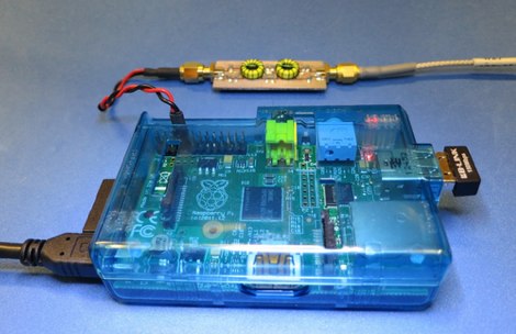
Now if you look at the picture above, there’s a little circuit between the RPi and the antenna… why is that?
On being clean…
Well, the RPi was never intended to directly output radio signal, so it generates a square wave with plenty of harmonics (unwanted frequencies above the desired generated radio frequencies) that pollute the spectrum if you connect the RPi output directly to the antenna.
NOTE: Having the privilege of sending radio waves worlwide comes with some small obligation: send clean radio signals! Don’t hurt your neighbour communications! Don’t force governments and regulators to limit our radio spectrum freedoms because we couldn’t self regulate. So far, HAM enthusiasts have done a great job not killing our radio passion. If you join, or plan on joining, please do the same.
Available Filters
So there are plenty of designs to make this output clean:
TAPR WSPR RPI Hats that work with their RPi OS image to transmit on various frequencies (20m wavelength (14 MHz): 14.070 MHz – 14.350 MHz for weak signal digital communications, 30m (10MHz): 10.130 – 10.150 MHz for weak signal digital communications, 40m (7MHz)).
Ok, if this looks like foreign unknown language, don’t worry, we’ll explain step by step.
DIY Filter
Now the goal of experimentation is to learn by yourself and make your own stuff, so below is the documentation of a design in progress (fun in progress? some people will call us crazy) of a custom filter, by non-electronicians, for the RPi. (You’ll see that we go slowly and step by step over the process we used, so that it’s easy to follow and reproduce).
The goal of this filter is to:
Learn about filters and electronic and RF,
work on 7 MHz,
for WSPR low signal (therefore low power, therefore we can maybe use some components such as Axial Fixed Inductors that are only for 0.25 W or 0.5W or 1W),
be built with low part number,
low complexity,
with easy to procure and to solder electronic components: no or low CMS, no exotic part numbers, no need to print a PCB mandatorily…
if possible no coil-winding (building the inductive coils),
if possible with protection of the RPi from static electricity coming from the antenna.
work on the RPi Zero W.
Actually, the goal of this post is to discuss between passionate individuals and critique the filter design(s) presented here, rather than providing a clean design.
So if you’re expecting a clean, profesionnal, working filter, this is maybe not the place.
Also, the goal is to document the (rather numerous) f..k-ups and mistakes we’ve done along the way, with their associated lessons-learned:
Using RC filter: originally selected because it is announced as the simplest filters, it worked but was extremely low-power output, due to to the very nature of Resistive-Capacitive (RC) filters, yeah, it resists and dissipates heat, therefore weakening to radio output power… logical.. Replace with Inductive Capacitive (LC) filter.
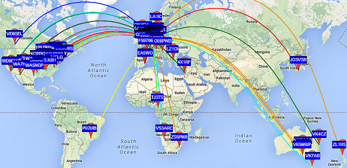
RPi can generate radio signals for a variety of bands, up to the FM band (around 100 MHz radio signal). This means that you have quite a lot of HAM bands (Legacy or WARC) you can use. The lower the HAM radio frequency, the bigger the antenna, the farther you can expect it to go: HF (3 MHz-30 MHz) can travel across oceans, VHF (30 MHz-300MHz) – UHF (300 MHz – 3000 MHz or 3GHz) range is only a few kilometers in usual conditions.
Usually antennas are one fourth or half the wavelength, so if you’re operating on 7 MHz, the 40 m band, you can expect your antenna to be from 10 meters to 20 meters wide, or high, or both.
That means that you usually choose your operating frequency based on the space you have. Typically, in cities, you will probably choose higher frequencies with smaller antennas.
And based on your antenna, you will pick a filter that is allowing only frequencies for this antenna to exit the RPi and go to the antenna.
Building an antenna is a lot of fun, and antennas are so varied, up to the ones that enable you to receive from and transmit to a satellite. It’s much easier than you initially think. We’ll have plenty of episodes related to antenna building.
So let’s build a filter… and please give us feedback
There are many types of filters, as stated earlier. We started with a RC filter but the drop in desired radio signal output power was too important, therefore prompting to choose another filter, an LC filter that should preserve better the desired radio signal power and still be somewhat simple to build with common components.
Of these LC filters, we choose a Butterworth pass-band filter, for its apparent simplicity. Critique is welcome.
Pass band means that only one range of frequency can go through. It’s opposed to Low-Pass Filters (LPF: Only frequency below the cut-off frequency can go through) or High-Pass Filters (only frequencies above the cut-off frequency can go through the filter).
$ brew tap guitorri/tap $ brew tap cartr/qt4 $ brew install qucs $ brew link qucs
Regarding installation on Linux, qucs was not in the APT packages of RPi. That’s because its Debian package was abandoned a few years ago. A lab member successfully compiled it using the official qucs wiki page on an AMD64 Debian 9 though, so there’s hope it might works on most distributions.
After this, we launch QUCS:
$ qucs &
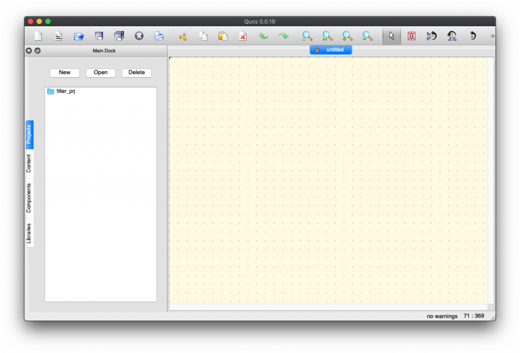
First fun is that QUCS runs but isn’t launched in the foreground, you need to Alt-Tab or Command-Tab to select its icon to see its window (otherwise you spend a good amount of time saying “wow… must be super awesome large software that takes ages to start… really long… such 31337 software…”. actually QUCS is quite quick to launch!):
To see larger version of these screen shot, just right click on the image and select “Open image in new tab” and switch to that tab. Full size yeah!!!
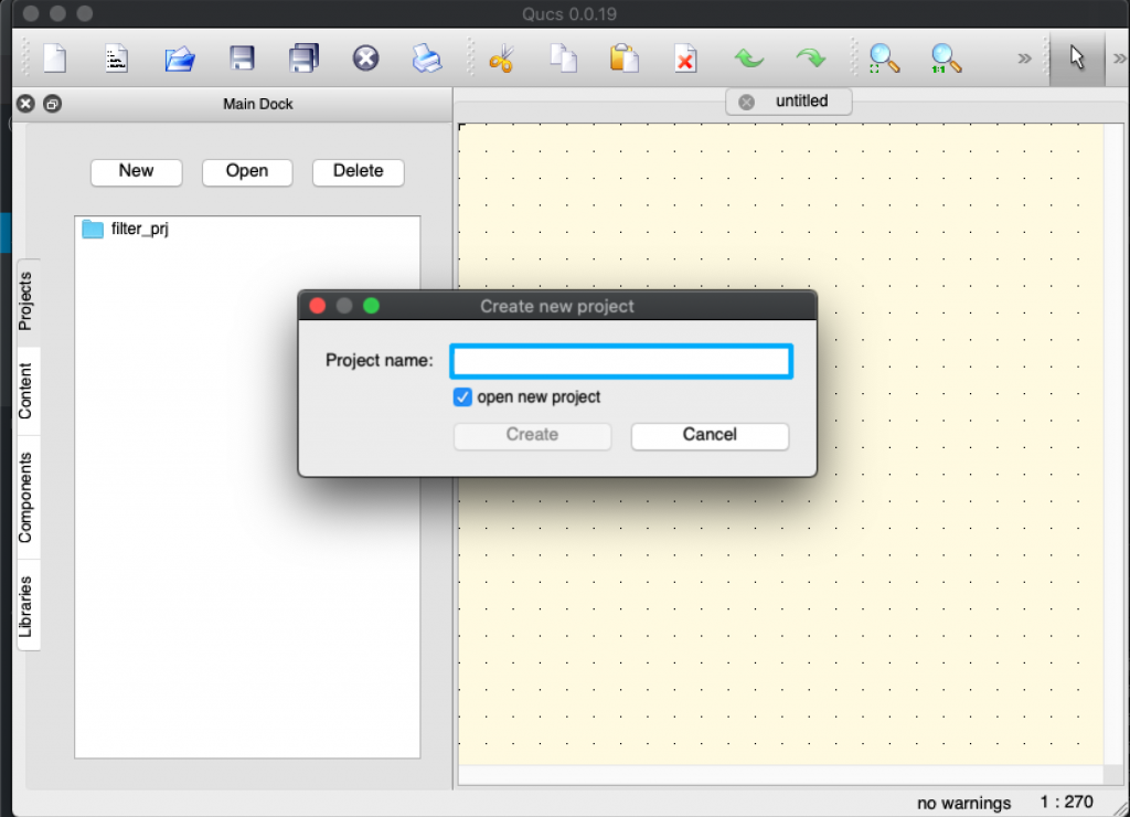
Then you can (and should) create a new project by Clicking “New” in the “Projects” side tab (here already created as you already see filter_prj).
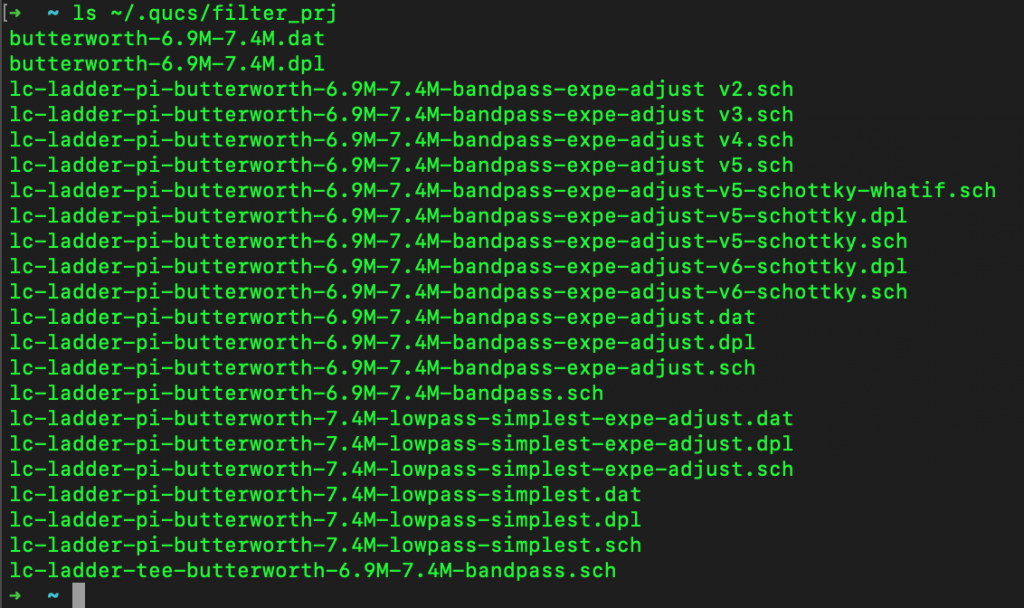
It corresponds actually to the folder ~/.qucs/<project_name> directory under which you’ll save all your schema files (*.sch). Creating the project directory will prevent some runtime errors when running simulations. Go ahead, create one and work there.
You can see above my quasi-OCD (Obsessive Compulsive Disorder) maniac naming style 😉
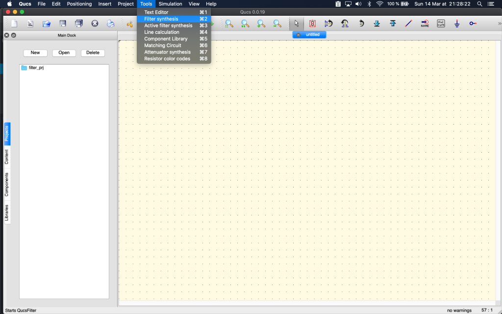
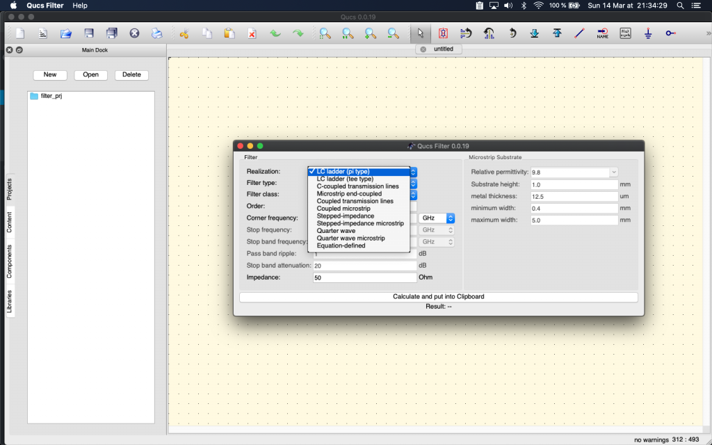
Then you go to Menu > Tools > Filter Synthesis:
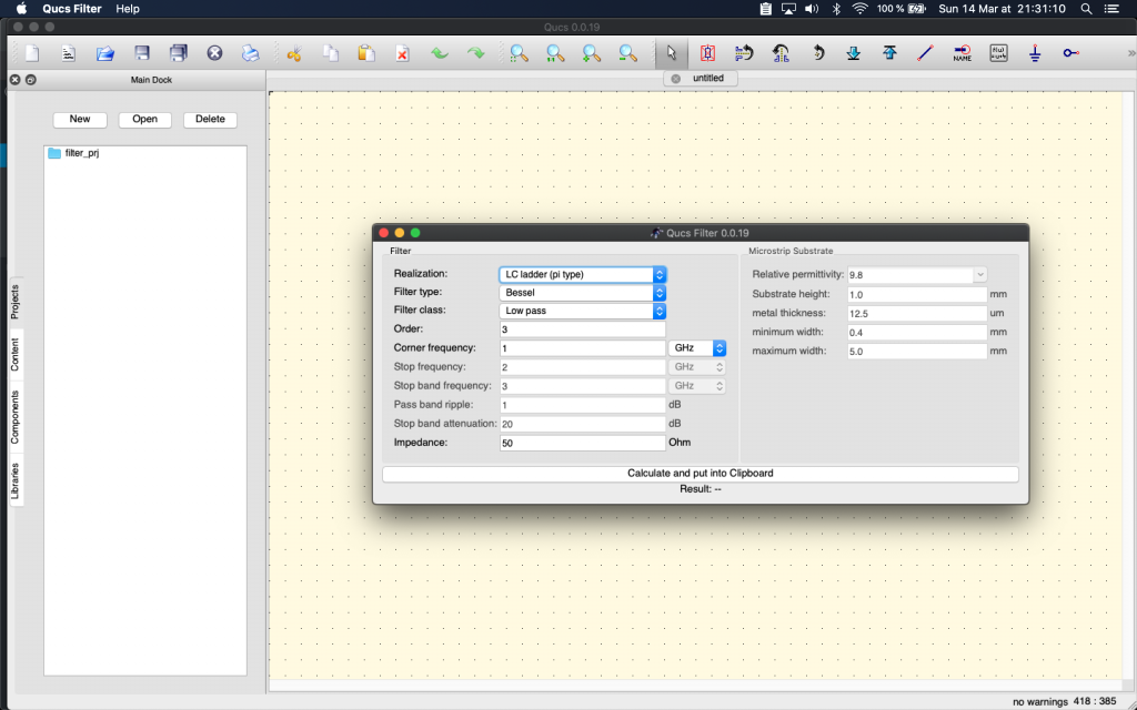
Qucs Filter is then run, but same thing as QUCS run, also often stays in the background. You’ll have to press ALT-TAB or Command-Tab to change window focus to it.
We choose LC Ladder (PI Type). Why? No idea. Suggestions are welcome. (In reality we rummaged through many web pages and many QUCS choices, comparing resulting filters with the simplest designs that were shown on the Net, before settling on this choice). Suggestions (and rationale) are really welcome about this.
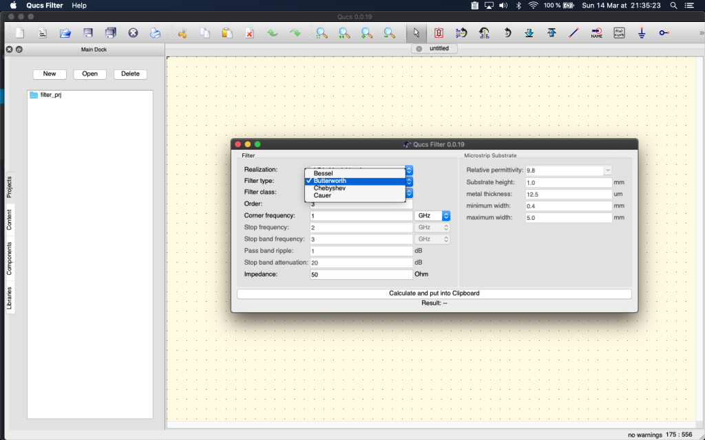
Then we change default type (Bessel) to Butterworth as it seems also to be a recommended LC type filter. (lessons learned not to use a RC filter and avoid signal power drops).
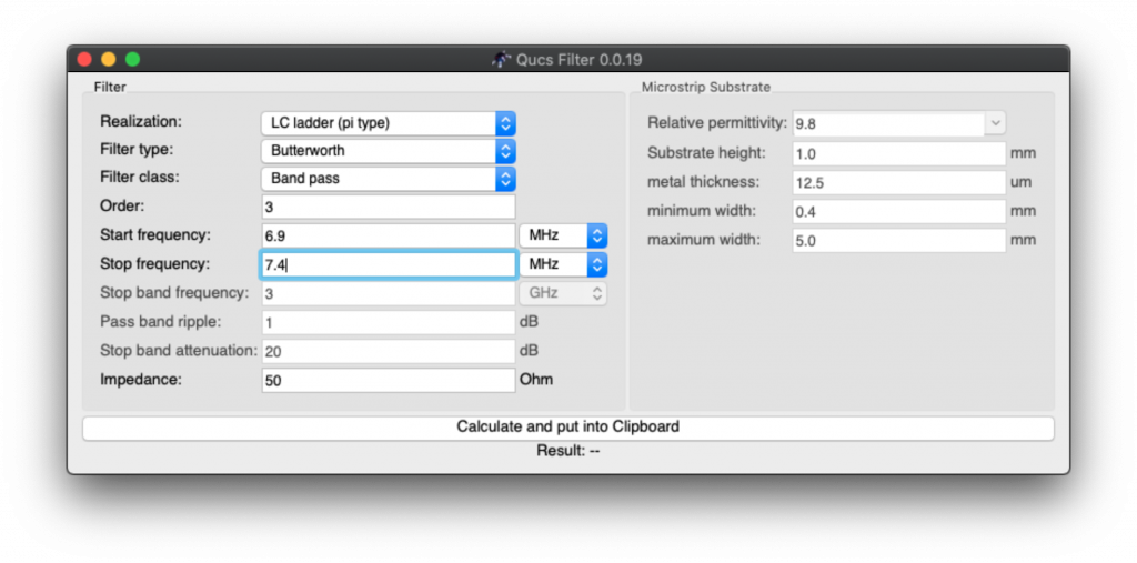
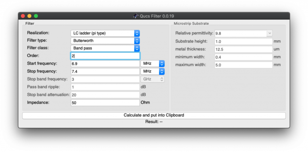
Then change default from Low Pass to Band Pass, and adapt start and stop frequencies, allowing for some “buffer space” around desired frequency.
Why this buffer space? because we’re going later to tweak values of electronic components to adjust with what we can easily buy, and therefore this will have an impact on the resulting frequencies that are allowed (that “pass”) or that are attenuated. Hence the choice to have some space around the 7 MHz HAM band frequencies.
The good thing is that the process described here works for all bands, you just need to adjust the values we’re specifying here. So if you want to build a filter for other frequencies, you can use this method and free software.
Here QUCS Filter with selected filters options and the frequencies input in MHz (note we changed the default frequency unit from GHz to MHz):
Then click “Calculate”
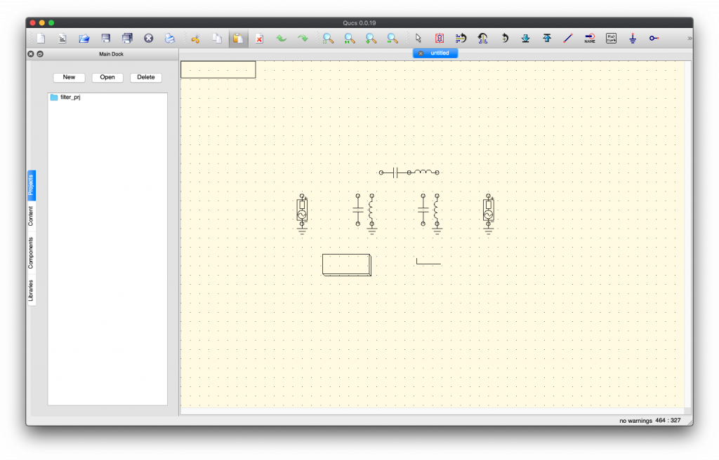
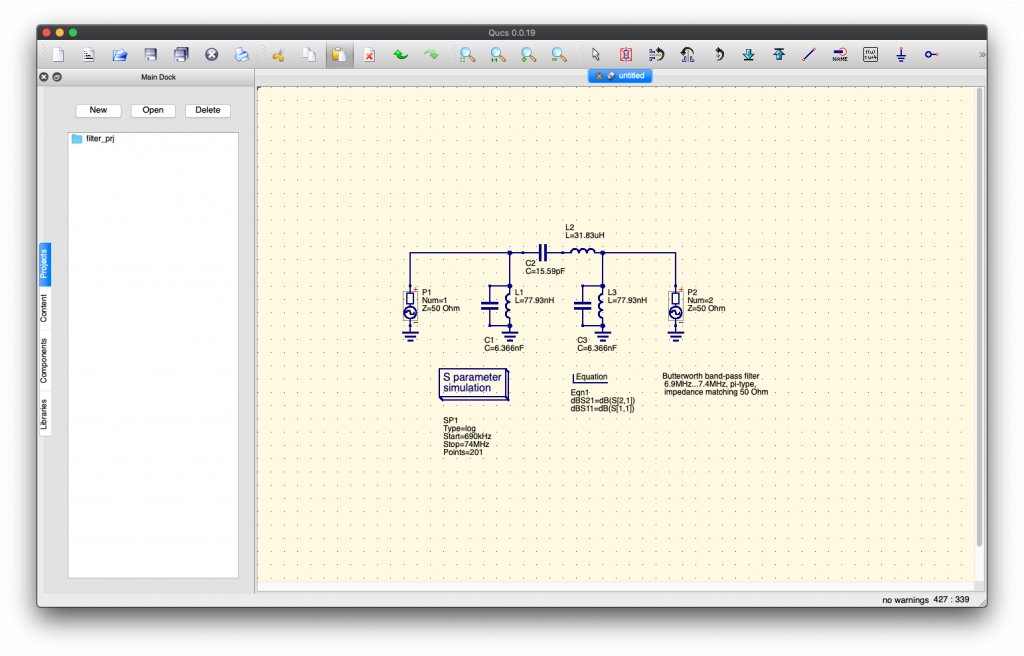
If you think nothing happens, well… you’re part right. It copied “something” (the result of filter computations) in the clipboard… then you need to switch to QUCS… and paste there in an empty circuit schema (Control-V or Command-V). A circuit skeleton will appear under your mouse cursor and hover on top of the schema for positioning of the filter result. That’s QUCS UX (User eXperience):
Move your mouse pointer to where you want your filter schema and click (Normal left click) to position it where you want on your page:
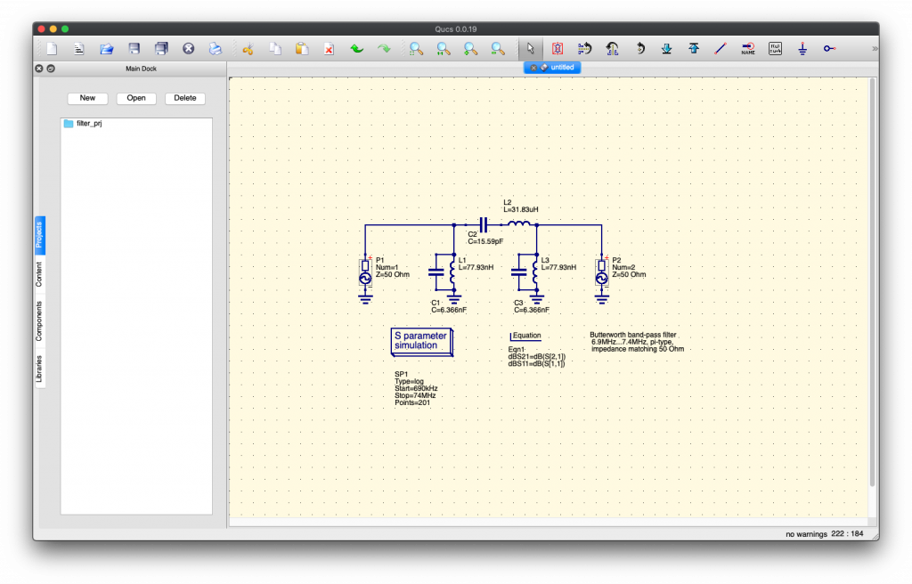
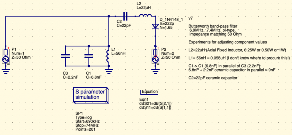
Tadaaa… the magic results appears on QUCS ! Argh… foreign unknown language again? We’ll explain later the schema.
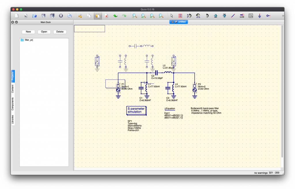
But if you continue moving your mouse, you’ll see that a copy of the filter is still selected, appearing as a skeleton (and can again be applied):
Yes… this is troubling UX. Just press ESC to deselect it (or “forget” it), it’s ok, one copy is enough and it is already there on your schema.
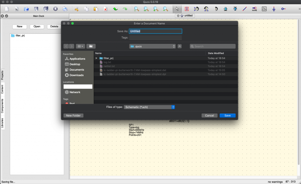
You can go ahead and save this:
Please note that we choose to limit the amount of electronic components in the final circuit schema by selecting in the QUCS filter not “Order = 3” but to “Order = 2”:
so yeah, you’ll need to repeat the process of generating a filter… that’s training 😉
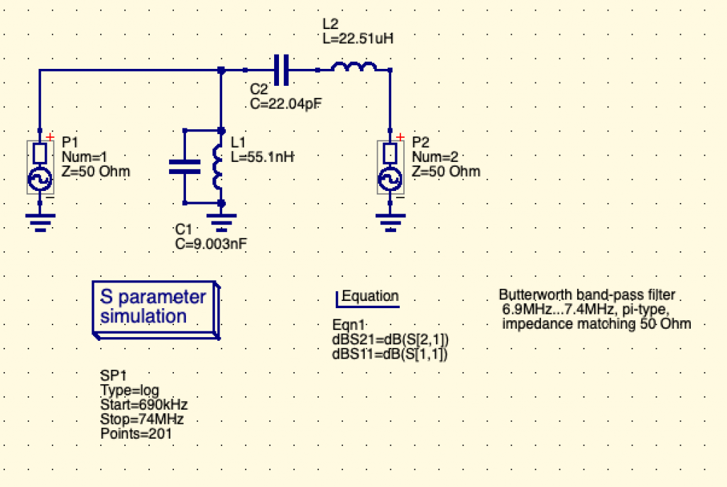
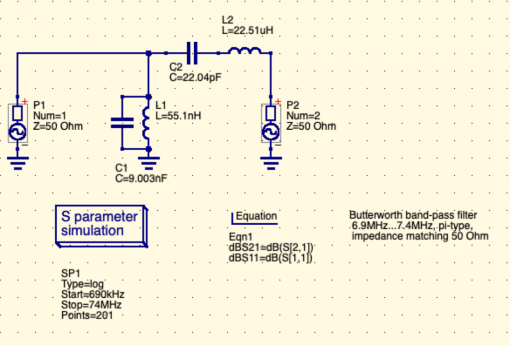
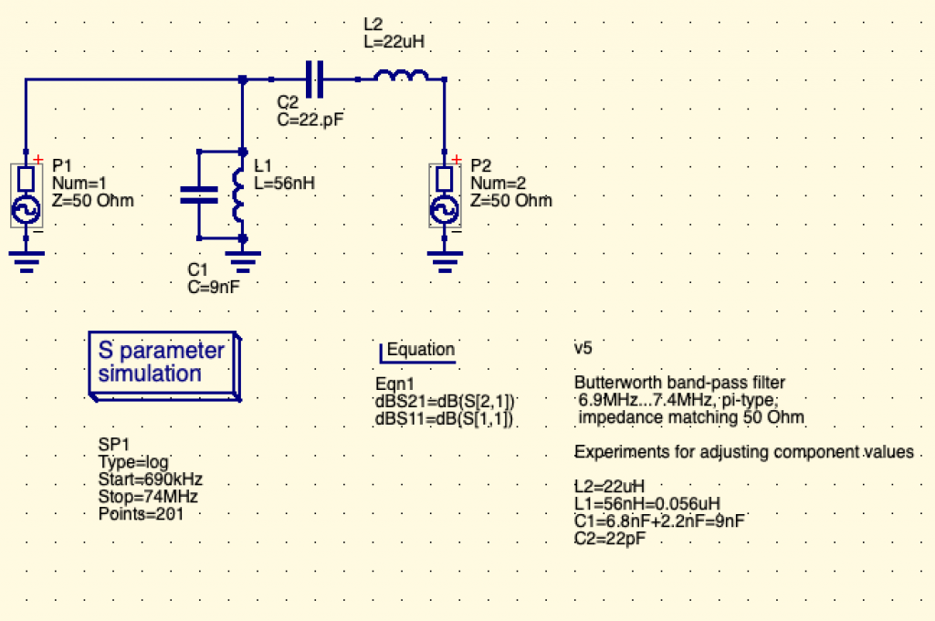
Resulting in this simplified schematics (with less electronic components):
Simpler isn’t it? — See, we have one less leg toward the ground with one less inductance “coils” and one less capacitor. Please also note that the remaining inductance and capacitor values have changed.
We don’t know really the impact of such choice, so don’t hesitate to tell us. It looked like the only visible impact (visible during simulation) was that the filtered signal would go closer to full values (1x the passed signal, 0x power of filtered values) with order=3, which means that our choice of order=2 means that the filtering nor the pass-through will be complete. That means that a small attenuation of the allowed band would still be applied by the circuit. It means also that the filtering would be less “selective” than and third-order circuit. It’s not so bad since at these very low power (RPi outputs only in the mW range), the attenuation of these very lower spurious signals is really sufficient and would not radiate enough to be a real RF interference to other radio spectrum users. Please tell us if we’re wrong!
As we understand this schema:
P1 (Port 1) is the generator, that is the TX output, the transmitter output:
Please note that it may be confusing as you see sometime “TX” label on some electronic schema for the input of the filter. It should be labeled “From TX” or “TX Output”.
P2 (Port 2) is the antenna (ANT).
It is also called sometime the “load” as you can output the radio signal to a resistive load to simulate an antenna (and avoid frying transmitters if they’re powerful enough and not connected to any “load”).
It’s very useful during design as it prevents badly designed filters from emitting real RF to an antenna.
Consider this when you start.
The antenna is really the output of the filter.
A little reminder on electronic components
Electronic components on a schema are prefixed by a letter that indicate the type of component, and then a number that indicates its identification on the schema and the value of such electronic component.
Let’s see common type of electronic components used here:
L: Inductors or Coils (“Bobines” or “Inductances” in french), these “store” energy as magnetic energy and give it back to the circuit.
There are many inductors types, most of the time these are coils of copper wire around a metallic ring “core”.
These are often used in transformers and amplifiers such as audio rigs, old power transformers, etc..
Some types are looking like resistors (one ceramic package traverse by a wire that is exposed on both sides)
C: Capacitors (“Condensateurs” in french), these “store” energy as electricity field energy and give it back to the circuit.
R: Resistors (“Resistances” in french), these pressure and limit the passage of electricity in a way that changes the Voltage (“E” in english, “U” in french) and Intensity (I).
There should be no specific resistor in filter circuits because resistors resists (!) and doing so, they heat up.
The heat is actually radio signal power that dissipates.
I.e.: the filter makes the whole radio signal power a bit weaker (or a lot weaker)
The look of resistors (one ceramic package traverse by a wire that is exposed on both sides) is very common. It’s often called the “through hole” packaging, since now there are surface mount (SMD) versions of it.
Let’s simulate now our new filter !
Now we have a filter, let’s see how it behaves in front of input frequencies. Nothing is better than a graph to “see” your filter. Here is how to generate this filter graph through simulation.
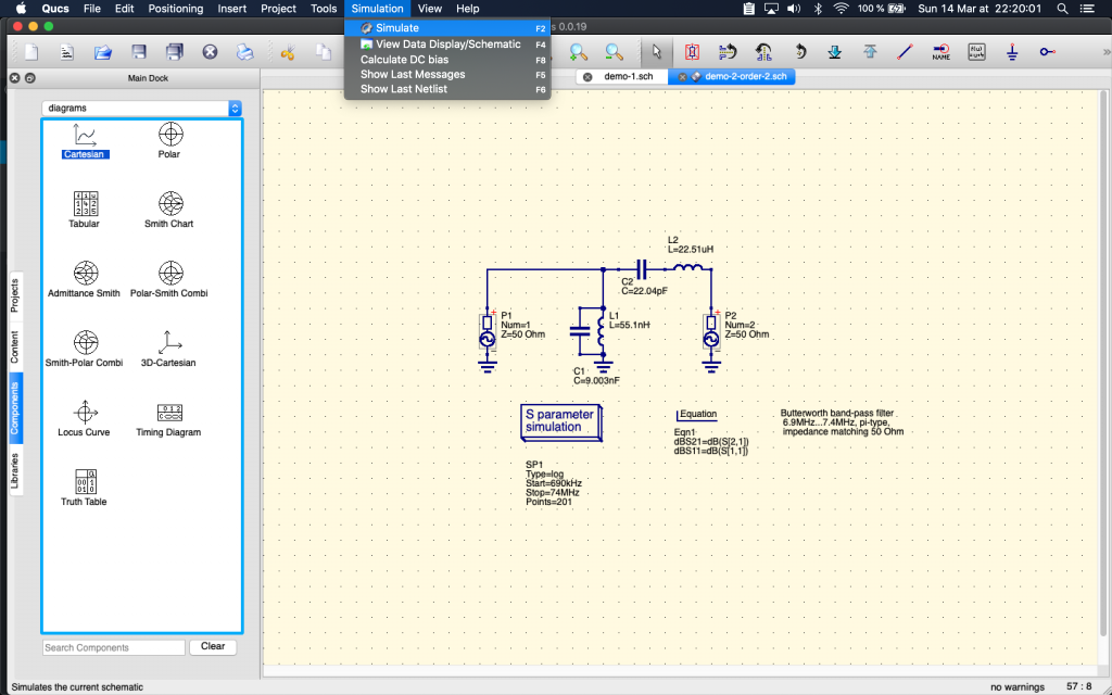
We click on Menu > Simulation > Simulate (or type F2):
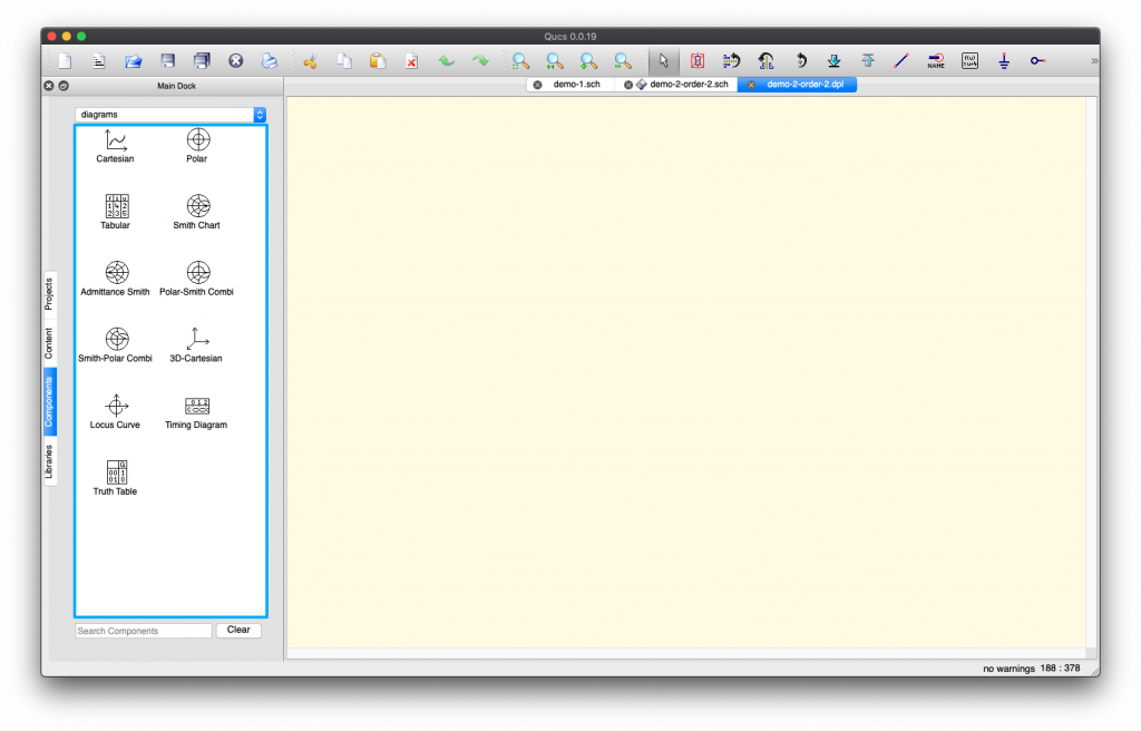
A new screen appears… But nothing happens: no simulation result.
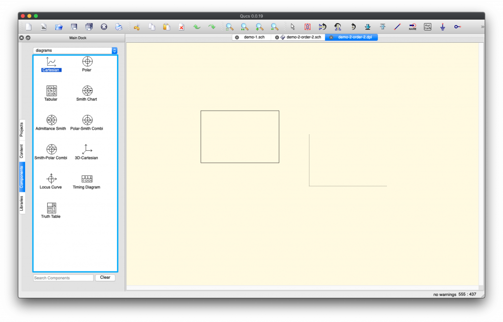
This is normal, QUCS is just waiting for you to chose which kind of simulation result you want to see. We’re going to chose Cartesian representation diagram, but the most elite radio guys will choose Smith (cuz it looks so cool! kidding aside, it must be awesome but it’s easier for newbies like us to read the simple graph):
Once you click on “Cartesian” and hover on the window, you see a “skeleton” of the result appear and follow you mouse. Just click (left click) once to instantiate the result, an option window should appear.
Now you need to set a few things for the simulation to run and result to appear.
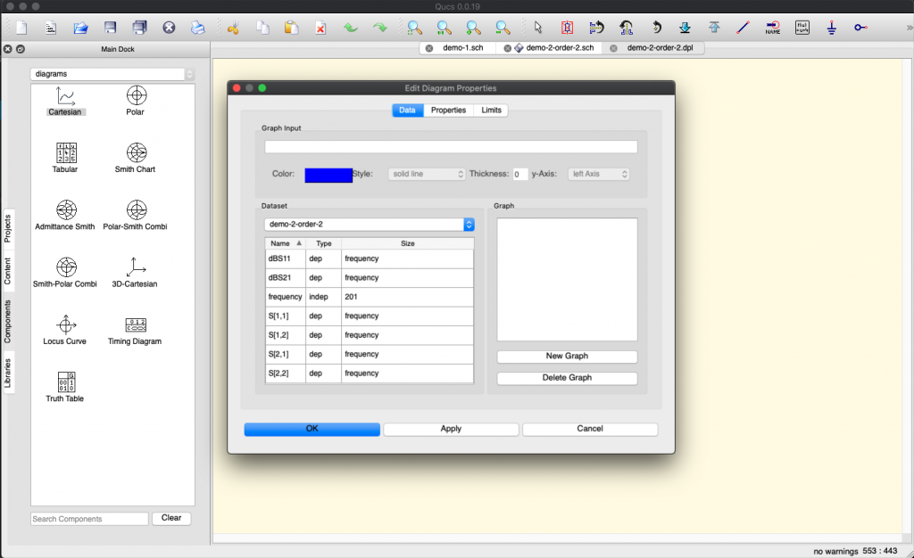
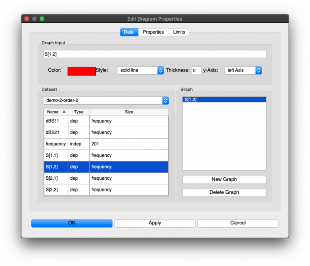
First you need to say which signals you want to be graphed. Here what we understand is that S[1,2] is the filter output signal (i.e. the filtered signal). So we’re going to double click on S[1,2] to add it to the Graph:
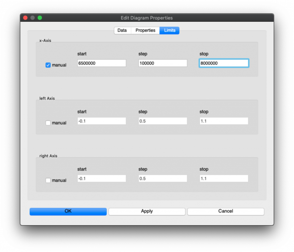
But it’s not finished, we now need to restrict the Limits of the graph to only the portion of the simulation we’re interested in. So Click on Limits, Select Manual input for x-Axis:
The values we selected are in Hertz (Hz) and quite large around the band so that we clearly see the filter output, and the step (100,000) is to prevent cluttering the graph.
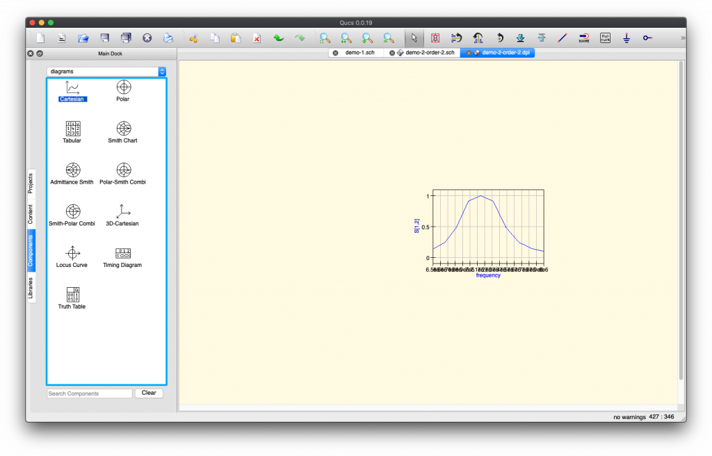
Then click “OK”. You’ll see a tiny graph appear.
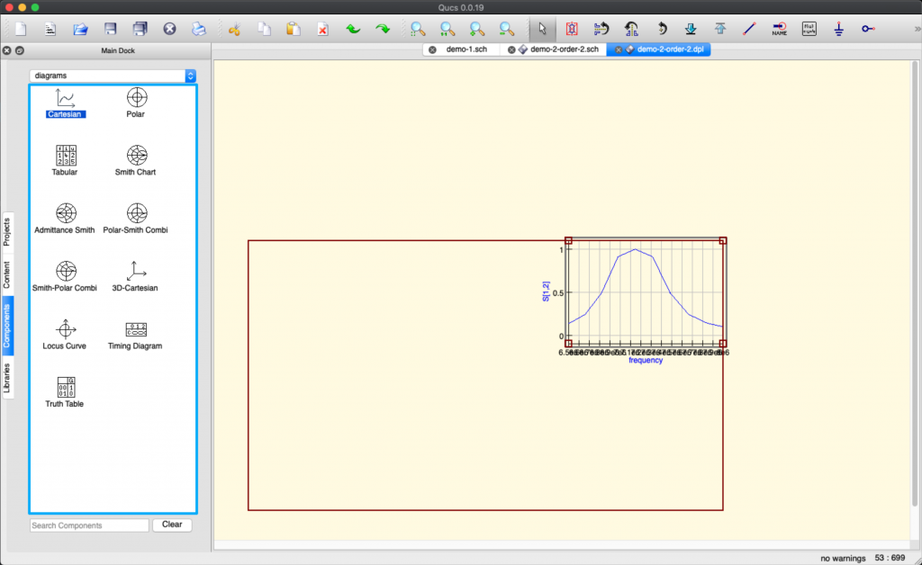
You can drag the corners by clicking into the graph and select one corner to drag in order to enlarge the graph:
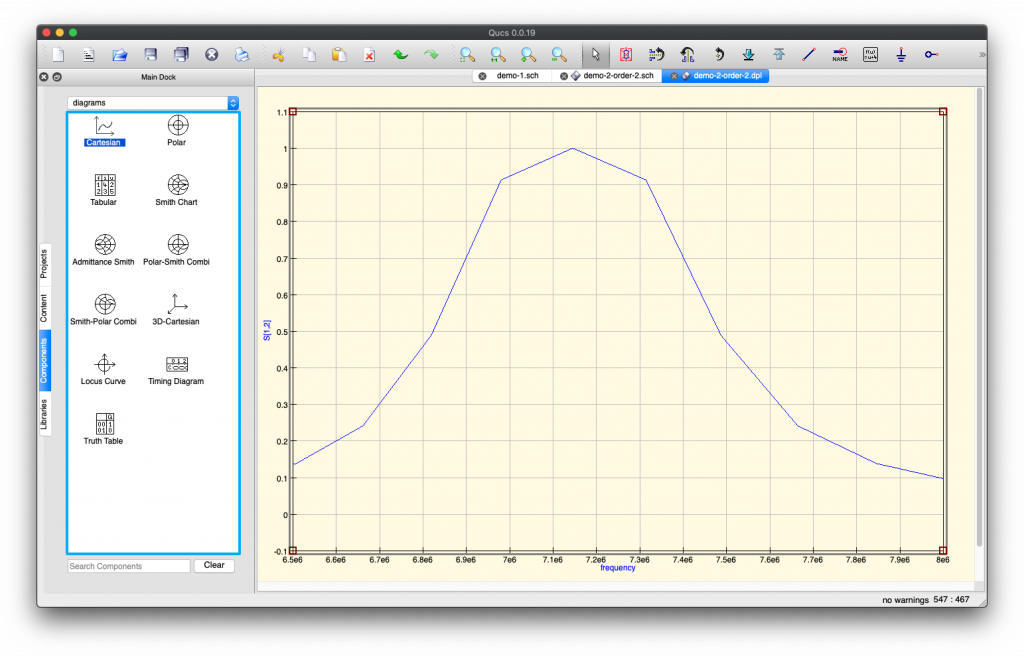
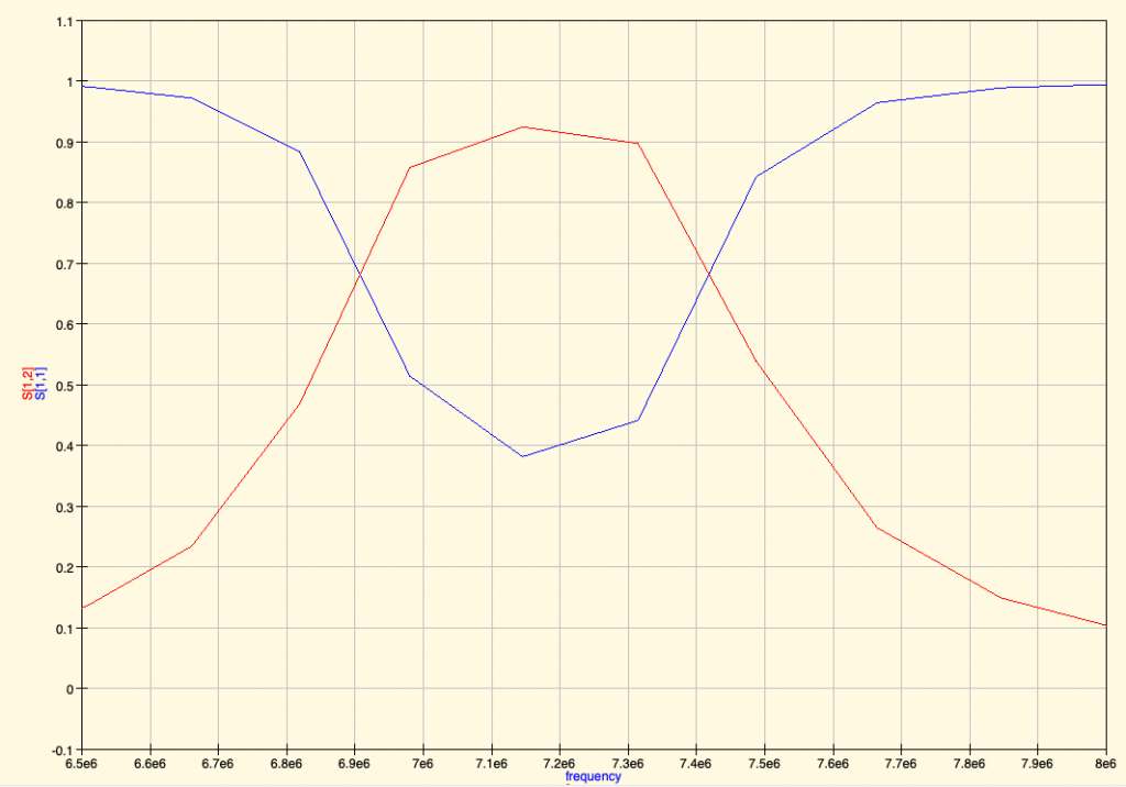
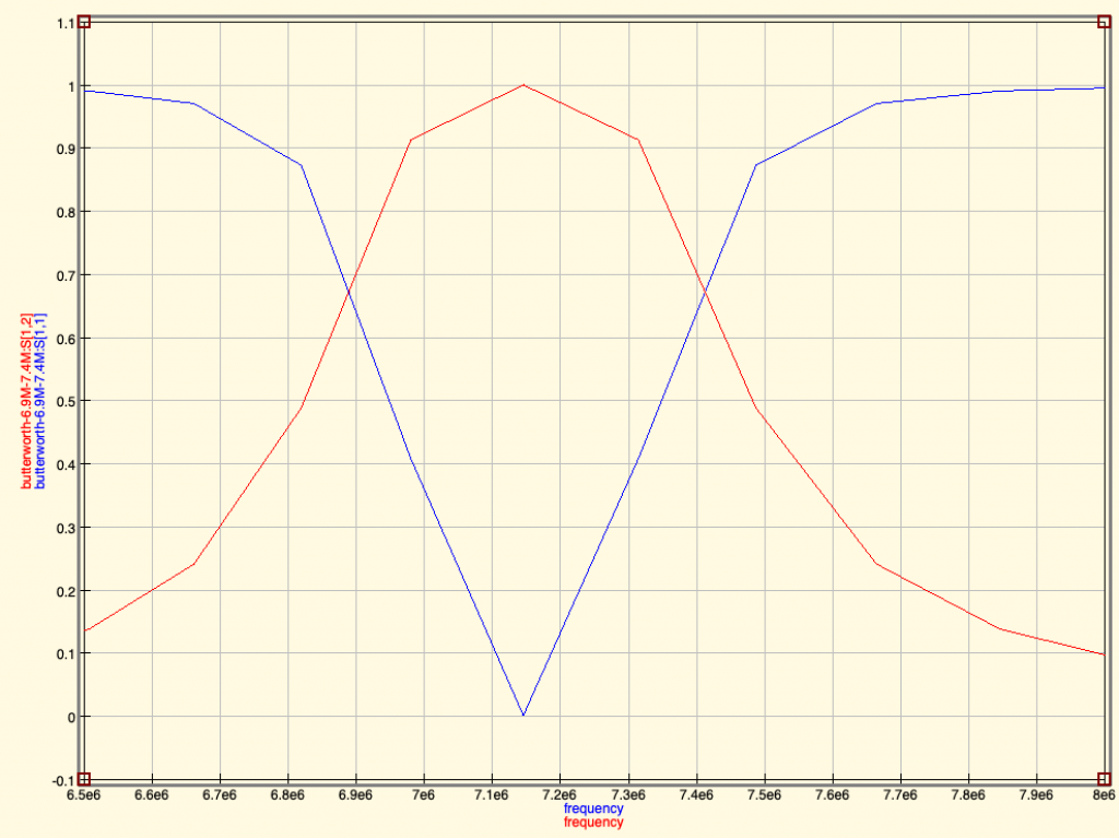
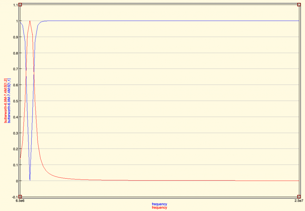
Then you have a nice result where you see in which frequencies your filter let’s the maximum of the signal go through:
We see that the band of frequencies specified is respected and let through by the filter, while the levels of other frequencies are very much attenuated. To read this diagram, the value on the Y-axis (on the left) is the number of times the power that goes through. The X-axis is the frequency. 7.1e6 corresponds to 7.1*1,000,000 Hz = 7.1 MHz
Now we need to adjust the components
As you’ll see, the values of components are not standardised values, and we need to change some of the components values to match what we can find in shops.
So we’ll do one change, save, run a simulation and check that the effect on the filter is not so bad. Not so bad effect means:
The filter still filters approximatively the same frequencies (same cut-offs)
The filtering level is still the same (around 0.1x of the signal or better)
The allowed (passed) signals are still around the same levels (0.9 or better)
So the raw values we had without adjustment of electronic components were:
Here is the adjusted graph we end up with:
All these values of components we can find in shops, except the L1 inductor that we can’t find. Suggestions welcome.
And the corresponding filter simulation output:
This looks acceptable. Or so we think… 😉
Now this is probably not how we should be building filters. And we’re open to suggestions or links to good resource to learn how to do better. It’s for sure not the Electronic Engineer’s way and we’re eager to do better.
Protect the RPi: Schottky Diode
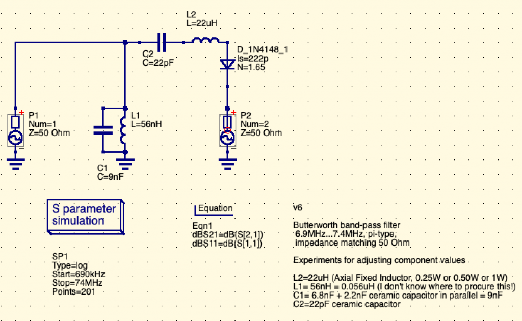
We heard (and felt with our fingers) that antenna can collect some static electricity, and that we may need to protect the RPi against such electricity using a Schottky Diode. Although not classified as Schottky Diode, the 1N4148 signal diode was often quoted as the way to go to protect our RPi. So here we go and added to the schema:
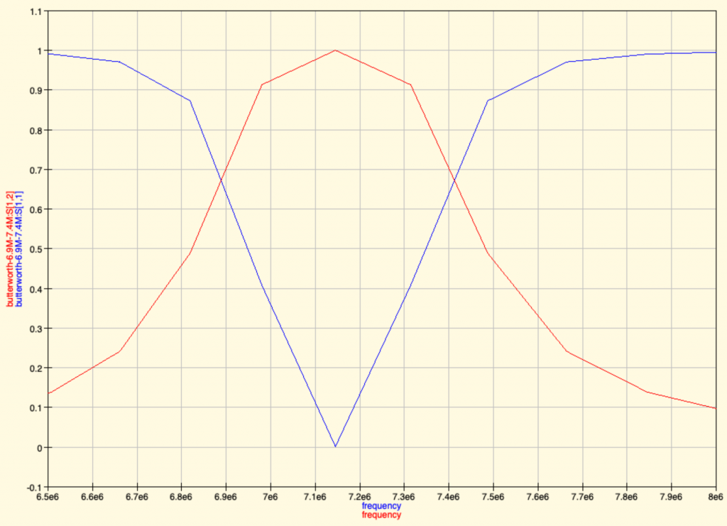
Then we proceed to simulate again to check the resulting graph:
(Even though some error window is displayed before showing Simulation result graph)
We see that the filter’s output seems ok.
Now that’s where we are for now. The schematics are here.
Update for off-the-shelf capacitor values
For completeness, here is the v7 with the split C1 capacitor to reflect reality of capacitors values that are easily available in shops:
Here we see that C1 became C1 and C3 (in parallel) to add their values. C1 and C3 (and C2) are standard ceramic capacitors (through hole versions).
And the resulting simulations gives the same result:
Feedbacks and comments
We’re eager to hear more from you if you have any question or feedback. Please either come to /tmp/lab Matrix chat room: #tmplab:matrix.fuz.re or comment on the reddit link (that will be posted in some time). We also expect to make a short video too to show people how we use QUCS for this.
Next episodes:
Building the filter: soldering, components, testing
Antenna connections and measurements with NanoVNA
Setting up antennas, safety considerations, emitted power
Building our next antenna(s)
Testing the reach of WSPR weak signals
In the meantime, kind regards and please, come and participate. There are no stupid questions. There are no bad feedbacks (but please be kind 😉 ).
Feedbacks and discussion
Ah… that’s awesome, the power of internet community, already just a few minutes after publishing some kind souls gave comments about the design and very informative resources, so I’ll take them point by point here.
Feedback #1: LPF
I would have used a low pass filter, not bandpass.
Yes, we tried some LPF (Low Pass Filter) designs and failed at getting a nice output (the cut-off was very slow and the levels not great). What kind of LPF would be best for this application? (as indeed it sounds like a good candidate)
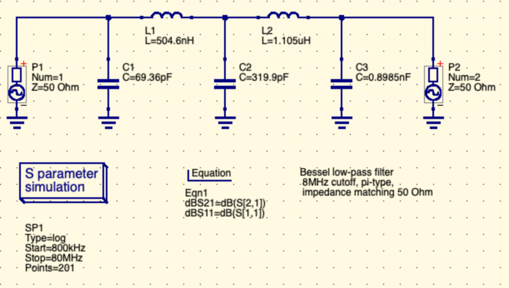
Here is a LPF design (along the lines of what the links below advised):
Two inductors, 3 capacitors. Here without optimized values for easy procurement.
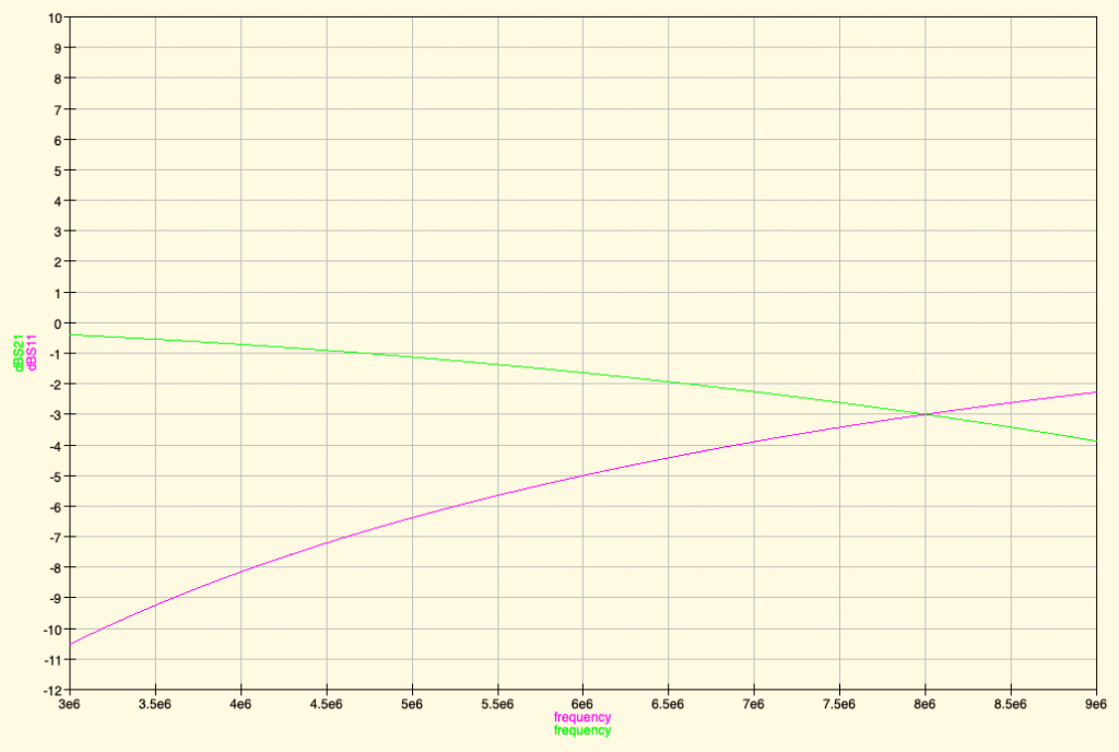
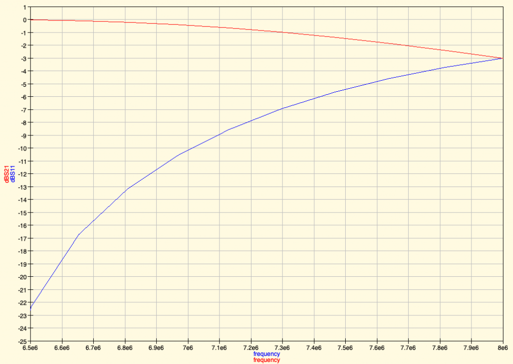
And then the simulation results (here we use dBS11 and dBS21 data lines to plot relative power drop in dB. Have a look at this table to understand the relationship between dB and power multiplier. To remember easily, +3dB is double the power, -3 dB is half the power. +6dB is 4 times the power, etc..):
What I subjectively find is that the cutoff frequency isn’t very “sharp” in simulation (supposedly it’s sharper in reality), and with the same amount of electronic components as a Band Pass Filter (BPF). Not sure what the benefit of the LPF would be.
What do you see if you model your filter at 2x and 3x the working frequency?
Here is the simulation result of our BPF (Butterworth Band Pass Filter) with very wide band, not sure that’s what was asked:
No bad effect in simulation… but that’s only a sim of course. Reality sometime differs wildly!
Feedback #2: Diode as harmonics source 🙁
Also not sure you should have the diode protection. Diodes cause harmonics so as quickly as you try to filter them you have placed a device to create more 🙁
Hmm…. how to test for this? Would the simulation show such harmonics Indeed it will be easy to test in reality.
It’s easy to add or take off anyway in the resulting circuit.
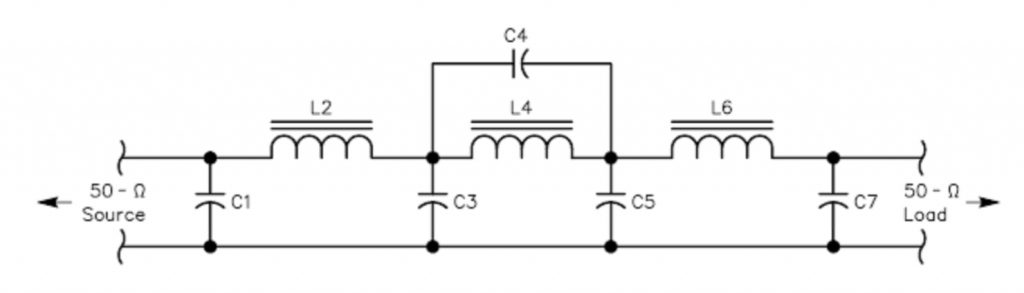
Maybe take standard values for low pass filters from webpages like http://www.gqrp.com/technical2.htm then change the inductance values to the nearest standard value fixed components?
3 inductors and 5 capacitors is definitely a doable and simple enough filter circuit, even if a little bit more complex than our DIY design, but in all probability more reliable and clean. The Capacitor symbol seems to indicate that it’s polarized capacitors that are used. Any feedback how important it is to use polarized capacitors here?
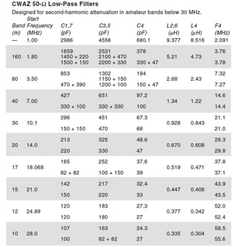
The band table values for components gives also the commercially available component values:
Also some nice ARRL article about the CWAZ filters mentioned in the above resources.
Reading about these filters the CWAZ filters advised by GQRP seems to be advised because of the inadequate filtering of Chebyshev LPF when power levels greater than 5W (FCC requires transmitter spurious outputs below 30 MHz to be attenuated by 40 dB or more for power levels above 5W)
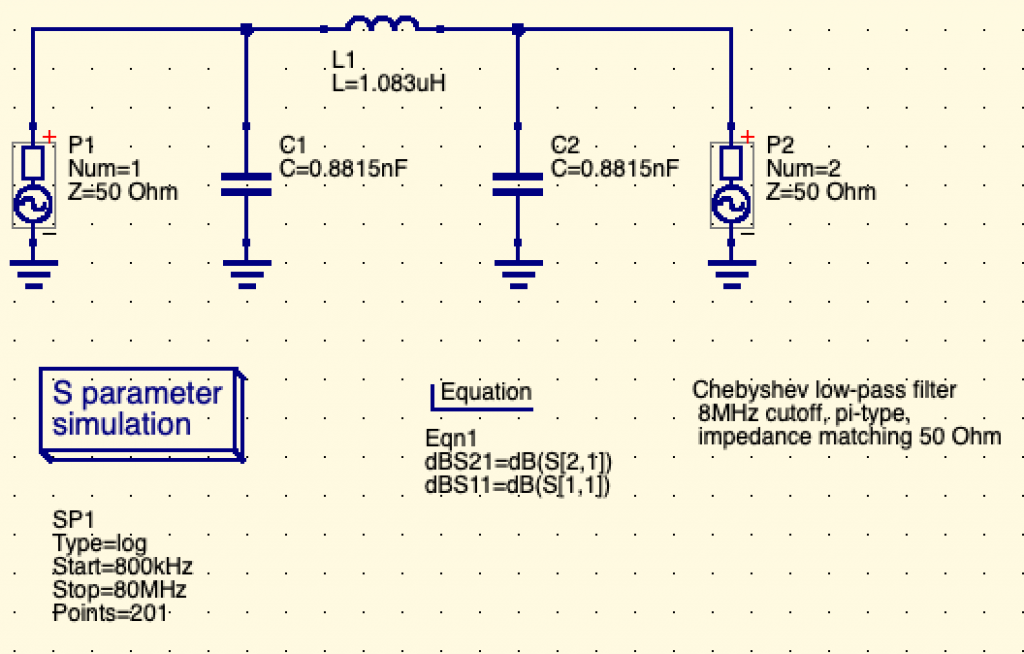
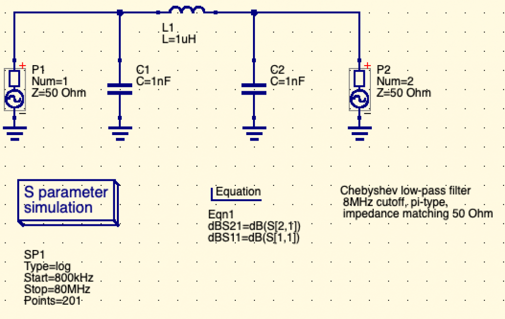
In our case, the power levels are far less than 5W, so actually we could maybe use a simple Chebyshev 3rd order Low Pass Filter and that could be good enough. The filter synthesis result of such LPF could be as simple as:
With resulting filter simulation:
Now when we adjust to available component values, this gives:
lc-ladder-pi-chebyshev-lpf-3rd-order-8MHz-v3.sch
How simple, 2x capacitor of 1nF, 1 inductor of 1uH. Now we’ll see if this fairy tale matches the reality of what we need once implemented 😉
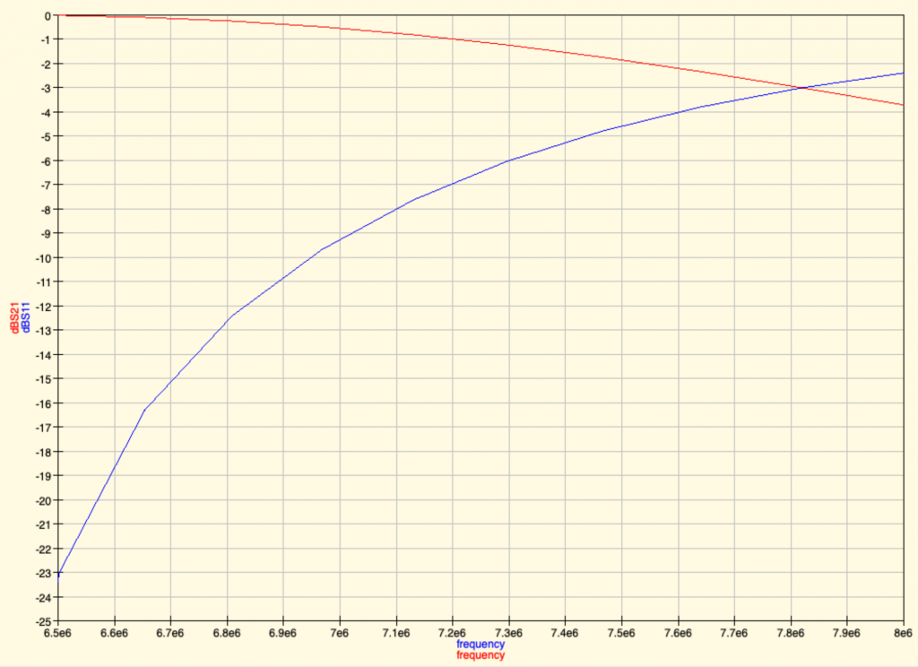
It simulates to:
Which seems pretty much acceptable. Do you think the same? Tell us.
Feedback #4: Filter may not filter enough at higher frequencies
The filtering of our simple filters may not be enough: the roll-off, that is the drop after the cutoff frequency, may not be steep enough.
Filters use often multiple “poles”, that is multiple Inductor+capacitor “legs” to the ground, in order to filter more (e.g. to -60dB or more) at higher frequencies. The more poles (the “higher order” filter), the steeper roll-off, the more attenuation of signal at higher frequencies.
More filtering means less spurious frequencies. And that is the goal of a better filter. Indeed, that’s the role of the CWAZ filter.
Note that Chebyshev filters use order 3, 5, 7 (odd numbers) only when doing filtering synthesis of a passive filter (i.e. one that you don’t need to supply external electricity power supply to work).
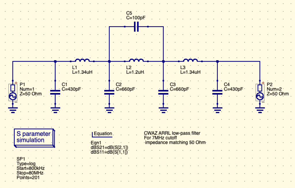
So that means that we may either try such filter synthesis…. or use the CWAZ filter that is quite simple still.
Now the problem is to try to use very standard values for electronic components.
Here for 7MHz, it’s a bit easier as 430pF is 330pF (standard) + 100pF (standard) in parallel. And 660pF is two 330pF capacitor (standard) in parallel.
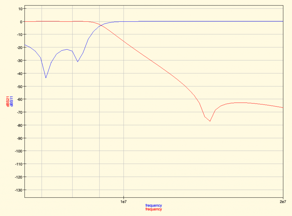
The resulting filter graph is actually very good:
Red line is the output of the filter. 1e7 = 10 MHz. 2e7 = 20MHz, so we see that around 9 MHz the signal starts to be filtered. And that a -70dB filtering means the power level was divided by 10 million 🙂
The inductor value of 1.34 uH is not at all easy to find in already prepared packages. If we replace this 1.34uH inductor by a 1.2uH inductor, there’s a risk for a mismatch impedance (meaning your antenna may reflect back some part of the signal to the raspberry pi and damage its circuit components). Ahh… so either we don’t filter enough or we risk having reflected signal from the antenna to the transmitter. What a wonderful world 😉
Future
The new plan is to try to build both our first DIY designed Butterworth BPF filter, the CWAZ and the LPF Chebyshev filter and evaluate these.
We’ll improve this article when finished studying these ressources! Thanks to everyone who is providing feedbacks and ressources!
Thank you
Thanks to the following awesome people who helped either with Radio or with the resources to post and document this exploration:
Mix’Art Myrys fait l’objet d’une fermeture administrative depuis le 20 janvier 2021.
Ce lieu toulousain nous est cher.
Sa vivacité artistique, aussi indépendante qu’originale, nous a toujours semblé exceptionelle. Nous n’en connaissons pas beaucoup de pareilles.
Mix’Art Myrys fait l’objet d’une fermeture administrative depuis le 20 janvier 2021.
Ce lieu toulousain nous est cher.
Sans compter les éditions du THSF (Toulouse Hacker Space Factory) qui s’y sont tenues, les universités des quatre saisons du Tetalab, ou la rencontre Sonoptic, ce lieu est un symbole. Sa vivacité artistique, aussi indépendante qu’originale, nous a toujours semblé exceptionelle. Nous n’en connaissons pas beaucoup de pareilles.
Au delà de cette éviction décidée en quelques jours, il apparaît aujourd’hui qu’il s’agit d’une opération coordonnée destinée à faire disparaitre ce lieu unique : la ville de Toulouse et le conseil métropolitain ont décidé en décembre de couper les subventions à l’association Mix’art Myrys en 2021 sans en prévenir préalablement l’organisation, ses salariés, les artistes, et les associations qui y résident.
Nous vous encourageons à relayer ces informations et participer au combat politique qui s’annonce visant à obtenir qu’une solution pérenne et satisfaisante soit conclue.
La résidence SONOPTIC, dont nous avons fourni un compte-rendu ici pour les aspects collaboratifs, a été une période de production assez intense pour la Teamlaser composée de membres du Fuz et du /tmp/lab. Nous allons exposer ce travail afin que toutes et tous puissent profiter des outils que nous produisons via liens et explications.
La résidence SONOPTIC, dont nous avons fourni un compte-rendu ici pour les aspects collaboratifs, a été une période de production assez intense pour la Teamlaser composée de membres du Fuz et du /tmp/lab.
Nous allons exposer ce travail afin que toutes et tous puissent profiter des outils que nous produisons via liens et explications.
Si vous ne connaissez pas la brique logicielle centrale de notre système nommée LJ, lisez plus bas la note qui le concerne sans quoi vous risquez de ne pas comprendre certaines informations qui vont suivre.
Cette partie est un peu hardue mais nécessaire. Afin de piloter les lasers via du logiciel libre, nous avons besoin de toutes sortes d’utilitaires et de processus résidents, voici ceux sur lesquels nous avons travaillé dans le cadre de SONOPTIC.
Mise au point d’un système de génération de programmes utilisant les pipes UNIX
Présentée simplement, cette solution permet de produire des lignes de commande comme ceci :
L’exporteur envoie ainsi dans la base Redis (cas le plus courant) les données générées par le generateur puis passées par les différents filtres.
Cela est possible grâce aux pipes UNIX, les "|" qui se trouvent entre les programmes. Ce sont des opérateurs en ligne de commande qui transfèrent au programme suivant la sortie standard du programme précédent. Ainsi, le générateur produit une liste de point qui passe de filtre en filtre avant d’être exportée sur le réseau.
Cette solution offre plusieurs avantages :
elle simplifie la démarche de création de programmes pour LJ : on peut utiliser toutes sortes de programmes et de langages pour générer des tracés, tant qu’ils ont une sortie (output, fichier, osc, etc.)
elle offre une grande capacité d’adaptation et de variation : on peut passer les génerateurs dans toutes sortes de filtres.
Cette solution a été particulièrement utile lors de la résidence pour prototyper rapidement des programmes.
Mise au point d’un système de transmission des spectogrammes et informations de tempo temps réel
Afin d’avoir une réactivité aux environnements sonores, nous avons développé un logiciel qui effectue des analyses temps réel ensuite envoyées au server redis central. Ce qui permet à plusieurs générateurs de points d’utiliser une source commune d’analyse.
Originalement développée en python2, elle est devenue complexe à compiler sur Debian et nous allons la convertir en python3.
Cette solution a été particulièrement utile durant SONOPTIC, notammment pour les systèmes de particules.
Il y a une grande différence ce qu’on envoie aux lasers et ce que dessinent ces derniers : leurs moteurs (galvanomètres) sont très rapides et ont en particulier tendance à “arrondir les angles” si on ne force pas leur dessin.
Ce travail a abouti à un filtre permettant effectivement d’optimiser les points d’un tracé, ce qui impliquait de supprimer l’optimiseur existant de LJ sous peine d’avoir une trop grande quantité de points. Un travail intéressant mais que nous devons benchmarker et intégrer dans LJ pour qu’il soit vraiment utile.
Mise à disposition du logiciel LJ sous forme de VM
LJ est un logiciel avec de nombreuses dépendances, prévues pour installer sur une distribution debian.
Nous avons donc entrepris de le fournir sous la forme de machines virtuelles via Packer. Pour le moment, seule une image KVM est disponible mais d’autres pourraient être déployées à terme permettant de tester le logiciel sur différentes plateformes.
La nécessité de ces images n’a pas fait ses preuves durant la résidence, entre processeurs ne supportant pas la virtualisation et personne préférant simplement utiliser le script d’installation standard.
Les pistes créatives poursuivies durant la résidence
En partant en résidence, les idées ne manquent pas. Voici celles que nous avons effectivement exploitées sur place.
Création d’un générateur de points basé sur les trames OSC et UDP
En utilisant des protocoles temps réel assez répandus et en les passant dans notre chaîne de traitement à base de pipes UNIX, nous avons pu recevoir des participations externes décidées sur place.
Ce type de receveurs de flux est très intéressant et montre la capacité de LJ à s’interfacer avec des sources hétérogènes.
Création d’un jeu en Rust avec contrôle par joystick
La création d’un jeu codé avec le langage Rust était l’objectif d’une partie de l’équipe, qui a recodé un moteur physique simple pour créer un jeu de plateforme interfacé à LJ via un exporteur en pipe UNIX.
Création d’un générateur de points utilisant une interface de détection de mouvements
Un membre de l’équipe a travaillé sur l’exploitation dans un cadre laser d’une double caméra infrarouge capable de reconnaître les mouvements de la main. Associé à une génération de particules, ce générateur a pu être utilisé en live.
Création de programmes de tracés utilisant l’analyse de spectrogrammes
Plusieurs programmes basés sur les analyses spectrographiques ont été développés. Les formes simples, comme un spectrogramme défilant, ont rapidement été jugées insuffisantes. Un système de particules plus complexe et plus réactif a été jugé beaucoup plus intéressant par le public.
Application d’un programme de simulation de particules moléculaires
Une chercheuse en biologie moléculaire qui utilise le logiciel Netlogo pour ses représentations spatiales a sorti en mode texte des simulations qu’elle a envoyé sur les lasers.
Création d’un pilotage de playlists laser via le clavier
L’utilisation des programmes en ligne de commande est peu pratique dans le cadre d’une performance live : interrompre le programme, changer la ligne de commandes, corriger les erreurs de frappe éventuelles…
Pour changer rapidement de programmes, un programme pour piloter une “playlist” dans un terminal a été produit. Il permet de créer / éditer / sauver une playlist de commandes et autres usages pratiques liés à une performance live.
Ce programme a été fort utile lors des restitutions, offrant plus de réactivité et de contrôle rapide des lasers.
Utilisation du logiciel OpenFrameworks pour piloter les lasers
Une personne a fait des tests concluants de pilotage des lasers directement via un plugin du logiciel openFrameworks connu pour simplifier l’interconnexion avec toutes sortes de périphériques, environnemens 3D, etc.
Quelques recherches visuelles avaient été faites pour explorer des visuels filaires fonctionnant en 3D anaglyphique (lunettes colorées). Un filtre a été produit à cet effet mais les résultats sont peu probants.
N’ayant qu’un temps limité, nous avons du faire des choix. Voici les pistes qui n’ont pas été suivies.
Utilisation à distance de synthés nozoid via une interface en ligne
Une interface en ligne a été produite pour les synthétiseurs nozoids que nous avions utilisés lors de précédents festivals. Nous n’avons pas eu le temps de faire de live à distance durant la résidence.
Création d’un générateur de points utilisant de la reconnaissance vidéos temps réel
Pouvoir tracer en temps réel un flux vidéo était un de nos objectifs. Après avoir identifié la librairie pypotrace qui pilote potrace pour reconnaître des segments dans une image en noir et blanc, nous avons essayé de lire des images vidéo depuis ffmpeg, puis depuis opencv mais dans les deux cas le débit était trop lent pour être satisfaisant pour du temps réel.
Gestion d’une platine en USB pour simuler des scratchs laser
L’idée étant de “scratcher du visuel” nous avions apporté une platine DJ en USB mais malheureusement celle ci ne disposait pas d’une connexion USBMidi fiable et le projet a été remis à plus tard, le temps de trouver un périphérique fonctionnel.
Affichage de textes élaborés sur place
Nous avions dans l’idée de diffuser des textes avec les lasers, mais avons abandonné l’idée par manque de temps et par souci d’adéquation avec les pièces acousmatiques diffusées qui ne se prêtaient pas nécessairement à ce type de visuels.
Utilisation des données de spectogrammes dans les jeux vidéos pour réagir à la musique
Par manque de temps nous n’avons pas eu l’occasion d’implémenter au jeu vidéo les événements audio.
Création de générateurs de points et de filtres utilisant l’analyse de tempo
Bien que partiellement implémentée dans un filtre nous n’avons pas utilisé cette possibilité qui aurait été utile si nous avions joué sur des musiques plus rythmées.
Association vidéoprojections et lasers
Cette piste était transversale à d’autres (reconnaissance vidéo / shaders) mais nous ous n’avons eu ni le temps ni les moyens techniques de l’exploiter.
D’autres idées ont émergé lors de la résidence
Idées venues en discutant et en observant les résultats de nos expérimentations lors de la résidence.
Idées créatives
Utilisation de micros répartis dans l’acousmonium pour avoir chacun son analyse de spectre
L’idée générale étant d’initier de nouvelles expériences avec l’acousmonium de Module Étrange, nous avons réfléchi à comment spatialiser l’analyse audio pour répondre aux évolutions sonores visuellement.
Une des pistes serait d’utiliser plusieurs sources de captation pour la spectrogrammétrie : au moins quatre micros répartis dans l’espace.
Création de paysages visuels associés à l’acousmonium
Simultanément à une meilleure détection spatiale des événements sonores survenant dans un acousmonium, il nous a semblé intéressant de réfléchir à une proposition graphique où les lasers seraient projetés sur différents “écrans” également spatialisés.
Création de nouveaux filtres : optimisation spatiale des formes
Certains des programmes conçus sur place ne s’affichaient pas en “plein écran” avec les lasers. Un simple programme qui redimensionnerait automatiquement ce qui lui est envoyé pourrait être utile.
Création de nouveaux générateur à base de particules
Les générateurs de particules sont intéressants sur les plans graphiques et conceptuels. Nous avons eu plusieurs idées pour en produire : simulation de partages ADN, comportements mutualisés, paramètres modifiables en temps réel.
Partage des points, attracteurs, et répulseurs entre plusieurs générateurs
La génération de particule utilise fréquemment des objets invisibles qui attirent et/ou repoussent les particules. Il serait intéressant que différents programmes puissent partager ces objets pour faire interagir leur production.
Utilisation d’un “Director Pattern” pour gérer les événements à envoyer aux lasers
Les systèmes de générations de particules sont “passivement réactifs” : ils n’ont pas de conscience de leur agitation et du spectacle qu’ils produisent. Importer le concept de directeur utilisé en intelligence artificielle pour les jeux vidéo permettrait de mieux gérer la tension dramatique des programmes, par exemple en modifiant lui même les paramètres des générateurs de particules pour augmenter / réduire leurs paramètres, ou les (dés)activer.
Utilisation d’appareils USB à touches / sliders / potentiomètres pour modifier les programmes envoyés aux lasers
Nous allons certainement continuer à expérimenter les dispositifs tactiles permettant de contrôler en temps réel les programmes de génération de particules. Ce qui nous permettrait d’activer/désactiver des comportements, ou d’en modifier les caractériques.
Utilisation de Machine Learning / DNN pour générer des textes lus dans les pièces acousmatiques
Il pourrait être intéressant dans le cadre d’une collaboration avec des diffusions acousmatiques d’utiliser les recherches contemporaines menées dans le domaine de réseaux neuronaux avec apprentissage profond et le traitement de la voix. Ceci permettrait de générer des textes visualisables et “lus” par des interprètes synthétiques.
Reconnaissance et mise a disposition des elements d’un visage analysé sur smartphone en temps reel
Nous disposons d’une librairie qui Utilise la reconnaissance faciale et permet d’envoyer les points d’un visage aux lasers. Il reste à déterminer dans quel cadre cette génération de points serait pertinente.
Création d’un programme adapté à une perfomance scénique utilisant la lumière (jonglage, prestidigidation, cirque)
Traduire et retranscrire en temps réel un spectacle vivant en jouant sur les ressorts de la lumière et de l’ombre pourrait être une idée intéressante, sous réserve de trouver des artistes intéressé.e.s par la démarche.
Utilisation d’algorithmes audionumériques pour les analyses de spectrogrammétrie et les programmes de génération de points
Dans le domaine des différents types d’analyse spectrogrammétriques. Nous utilisons essentiellement la Transformée de Fourier pour l’analyse spectrale, mais il existe aussi entre autres :
Analyse du son non Fourier
Analyse par banque de filtres à Q constant
Analyse par ondelettes
Analyse du signal par distribution de Wigner
Analyse spectrale par autorégression
Dans le domaine des filtres audio numériques. Par exemple implémenter des phénomènes de réverbération, de passe haut / passe bas, de délai, etc.
Amélioration de la partie détection de tempo
Cette partie pourrait être très intéressante dans le cadre d’une collaboration avec des musiciens électro. Pour l’instant la logique et son implémentation est trop naïve. Nous pourrions utiliser des standards existants ou développer notre propre formule en la perfectionnant.
Technique
Analyse du code et des solutions utilisées par OpenLase pour le tracé des points et la vidéo temps réel
La solution OpenLase / Github qui dispose de bindings python semble atteindre des performances intéressantes dans différents domaines. Il serait judicieux de mener une analyse pour comprendre de quels processus nous pourrions nous inspirer.
Solutions d’optimisation des points afin d’améliorer le tracé
L’optimisation des tracés est un processus clé pour les lasers : trop de points et le tracé ralentit, pas assez et il devient imprécis. C’est l’objet de plusieurs recherches académiques et de diverses implémentations qu’il faudrait intégrer au mieux dans le système.
Creer un exporteur TCP en plus de celui via UDP
Afin de favoriser les lives à distance, un exporteur en TCP pourrait améliorer la qualité du transport pour les collaborations sur Internet.
Creer un exporteur vers le simulateur web
Le simulateur web nous permet de prévisualiser ce qui sera envoyé au laser. Une solution envoyant les listes de points dans une page html locale via websocket sans avoir besoin d’installer LJ serait intéressante.
Intégrer une synchronisation via des timecodes réseaux
La synchronisation de vidéos et de musiques est possible via des solutions de timecode comme MTC et SMPTE. L’idée serait de généraliser cette synchronisation dans les programmes laser, par exemple en utilisant le projet timecode generator disponible sur
Rappel : le logiciel LJ
Voici donc un point sur le logiciel LJ qui se trouve au coeur de notre système.
LJ est notre outil de pilotage des lasers. Il démarre des services qui s’interfacent entre les clients qui generent des points et le hardware (tracé par les lasers) :
Un serveur de websocket communiquant avec des pages web (voir plus loin)
Un serveur OSC proposant également l’interaction avec l’ensemble des fonctions disponibles
Une interface vers differentes synchronisations : Artnet, midi, Link.
Les tracers qui envoient les informations aux lasers (via etherdream)
Un gestionnaire qui relaie les informations entre les composants
L’un des nombreux avantages de LJ est son interface web qui permet de changer en temps réel les paramètres des lasers pilotés (taille, position, nombre de points par seconde, intensité, etc.) mais aussi de simuler les points qui sont envoyés au laser via un canvas HTML5.
Un aspect fondamental de LJ est l’ouverture à de nombreux protocoles, notamment pour recevoir les listes de points à tracer et le partage d’informations en temps réel. À cet effet, LJ utilise la base de données clef/valeur REDIS pour stocker les points qui seront envoyés.
Une note au sujet des licences : l’auteur original de LJ n’est pas un fan de licences et avait choisi une licence Creative Commons, malheureusement déconseillée pour les projets logiciels. Une discussion interne est en cours pour décider de la meilleure licence pour le projet (GPL copyleft ou MIT/Apache).
Enregistrement de la projection laser réalisée lors de la diffusion d’une pièce acousmatique de Rémy Carré, le samedi 10 octobre 2020.
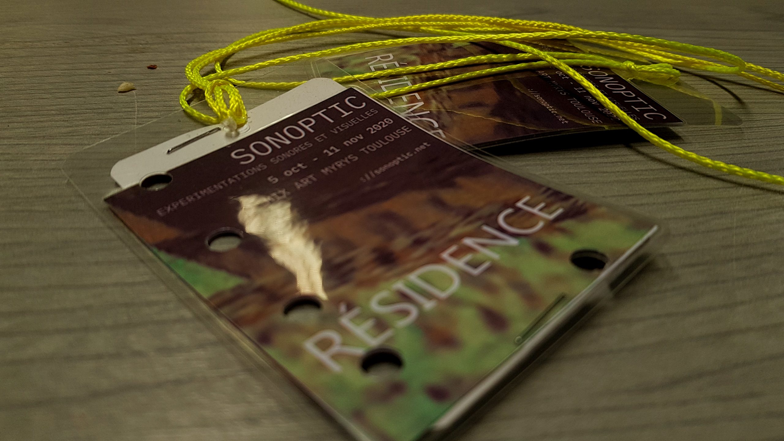
À l’invitation de MixArt Myrys des membres des hackerspaces /tmp/lab et Fuz ont participé à la résidence de l’événement SONOPTIC à Toulouse du 5 au 11 octobre 2020.
Il serait trop long d’énumérer ici les rencontres, discussions, et projets qui auront essaimé cette résidence, en voici néanmoins un compte-rendu général et partiel.
L’ambition de SONOPTIC était de pousser l’expérimentation sonore et visuelle. Pari réussi, au vu de la qualité des échanges et des productions.
Après quelques jours de workshop entre artistes, le public a pu malgré la COVID19 visiter les expositions et assister à des restitutions et des lives préparés lors de la résidence.
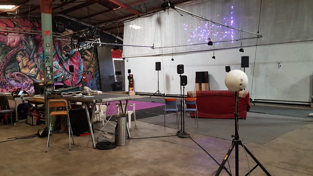
Une des installations présentées dans l’exposition.
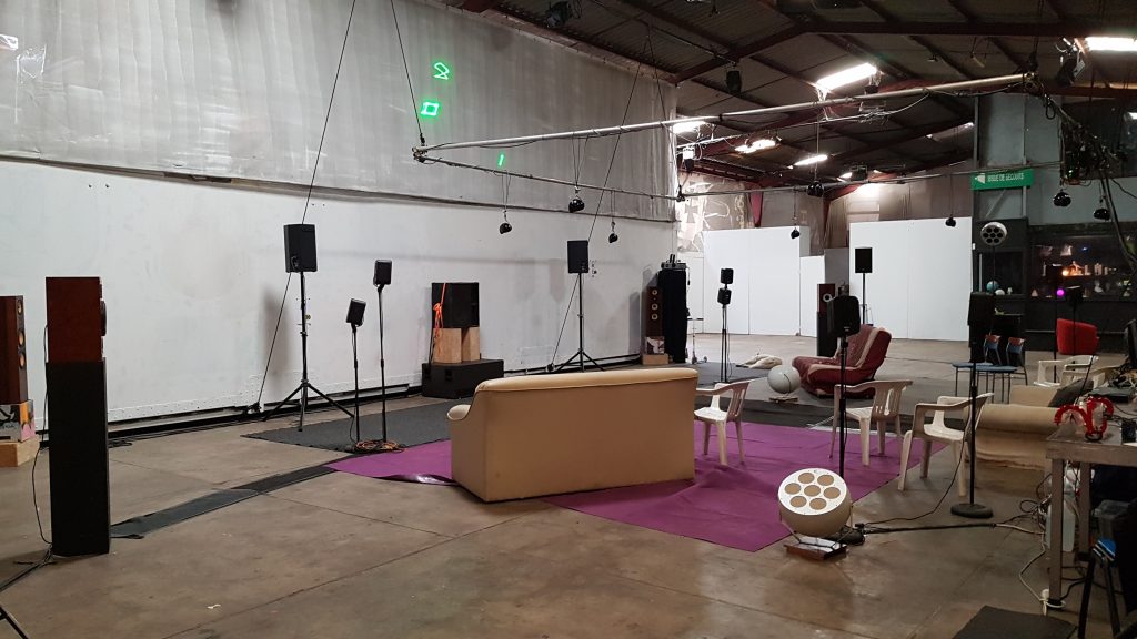
Nous -membres des collectifs /tmp/lab et Fuz- avions été placés dans l’expace mutualisé, une grande salle ouverte à la circulation que nos voisins –membres du collectif “Module Étrange“– avaient sonorisés avec plus de 40 enceintes : un acousmonium exceptionnel dont nous avons pu profiter durant toute la semaine !
L’acousmonium a aussi servi pour diffuser les pièces acousmatiques d’autres musicien.ne.s, comme Melodie Duchesne ou Rémy Carré.
Les expérimentations de lasers dans une dimension artistique renouvelée étaient notre choix de médium pour cette résidence, avec quelques pistes créatives comme trame d’expérimentations. Nous les détaillerons dans un prochain post.
Les lasers ont été l’occasion de collaborer avec plusieurs personnes
Nina Verstraete, chercheuse en génétique moléculaire : affichage sur le laser de plusieurs simulations de bactéries
Tth, hacker au Tetalab : Pilotage en C d’un joystick
Rep, artiste visuel : expérimentations des capacités du logiciel OpenFramework pour le pilotage de Lasers
Aux organisateur.ice.s de Sonoptic, tous nos remerciement !
Et à tou.te.s, notre joie d’avance de participer à une prochaine édition !
Covid19 won’t block us! So let’s go virtual. We’re going to organize a virtual Kubernetes Security tech session soon so that interested people can join and share experiences about this. Goal is to look into:
Seccomp
AppArmor
Capabilities
Nodes isolation and security
Admission controllers
K8S Scheduler and controller
APIs Security
Misc CNCF projects such as:
Vitess
Jaeger
Lyft’s Clutch
Spotify’s Backstage
KOPS
For now, best way to show your interest is to join a newly created RIOT Element chat room #tmplab-public and say you’d like to participate.
Depending on interest, we’ll chose a date for start. We’ll then update this page (or post a new one) to announce dates and start.
Discover how to install bots for Matrix, a fun and exciting federated protocol
Matrix is a fun and exciting federated protocol that we’re using more and more at /tmp/lab.
If you want to join the discussion, head to our riot channel and check it out!
Riot is a well-known web GUI for the Matrix protocol which could be defined as “a chat interface between IRC and Slack”. It’s cooler than IRC to some extend – backlogging is easier- and it is free software, not like Slack 🙂 Still, IRC, Slack and Riot have in common a capacity to use bots, and that’s what we’ll be drilling today: Matrix bots. Onward, my mechanical steed!
Note: Our privacy-aware assistance might interject here with some well founded critics of the Matrix ecosystem, which is not free enough as of now. Find here a list of concerns as a github issue tracker for more information.
Well, first, it’s python, which we like. Also, it’s actually well coded: Tulir Asokan -the author- did an impressive work at providing his own implementation of the matrix api which he plans to use to provide a number of bridges. It is modular, meaning that you can extend the functionnalities in a clean manner. And that leads us to hackability, writing your own plugins should be easy with maubot, more on that soon hopefuly.
Deploying Maubot on a server
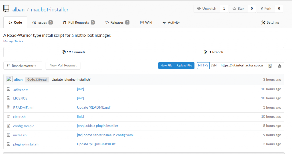
Though maubot proposes a docker install, we were not fans of that for system administration reasons. So we’ve made an install script in bash you can find in this git project.
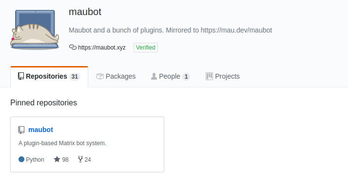
The maubot installer project
This install script should really simplify your job. Assign in the DNS a subdomain name -say botsinspace.example.com- to your server IP address and the installation should be as simple as
git clone https://git.interhacker.space/alban/maubot-installer.git
cd maubot-installer
bash install.sh
After indicating your chosen subdomain, you can go for default answers, including the matrix.org homeserver, and should be fine for the rest of this tutorial.
Et voilà ! You should have a maubot instance running with Letsencrypt on https://botsinspace.example.com
Creating your first bot
Once the maubot instance is up, understanding the maubot concepts will help you configure it.
Plugins
Plugins are the bots “brains”. They are python code and configuration files, ran in background by maubot. Ther are stored on the server as mbp files, which are archives using a zip compression.
Clients
Clients are the bots “physical presence”. They are in fact user accounts on matrix servers, no more no less.
Instances
Instances are associations of a plugin and a client. Once you have an instance, you have a bot!
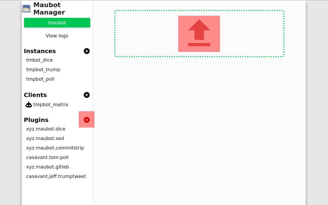
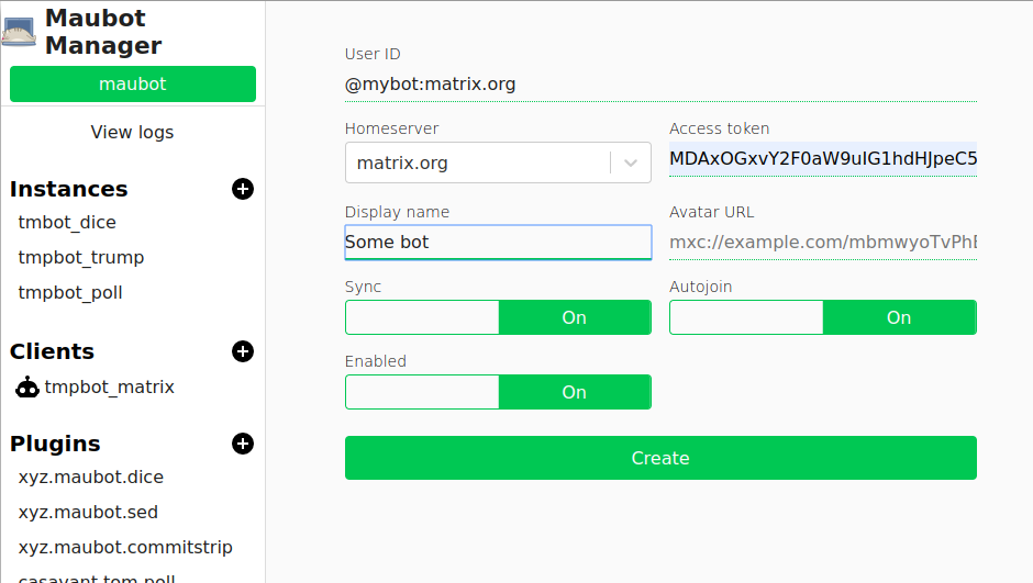
Log in your maubot instance, click on the plugins “⊕” button. A big UPLOAD button (cf. screenshot) shows up, click on it, select a plugin zip file on your disk, and there you go !
The maubot plugin menu
Easy right?
Well except one thing: where do you get that zip file in the first place? From the github “Get a zip copy of the project” button of a plugin page? Well, nuhuh, nope, that won’t work. Maubot will reject that zip file. Why? The github zip file contains the file “in a directory” called “$projectname-$branch” and maubot expects files to be at the root of the zip archive. So, the right way to go is: ٭ Download a zip file from a plugin repository home page ٭ Extract it locally ٭ Enter the newly created directory ٭ Select all its files and sub-directories ٭ Create a new zip archive with these ٭ Upload that zip file to maubot.
Or if you will, plugins might available as “mbp” files in the “release” section of their github page. Sadly, they’re not always up to date, so you might be left with a manual job to do.
Option 2. Use the command line interface
Well seeing this could be a bit complex and annoying to repeat we came up with a script in the “maubot installer” project, called plugin-install.sh
You will need to use a config file or edit the variables at the beginning of the script for it to work though.
Once you’ve done it you just have to ٭ Run the script ٭ Select a plugin in the list ٭ Login (once only) with your maubot user and password ٭ And the script will call the “mbc” executable provided by maubot.
It is worth mentioning that some plugins might require a few additional dependencies. For example the trump plugin required to run an install command in the virtualenv of the project:
cd /opt/maubot
source bin/activate
pip install Pillow
But now, you should have at least one plugin available. Let’s head to the next stop.
Add a client
We won’t cover here the run-your-own-bot-factory approach, which requires running your own synapse server, in other word running your own matrix instance. So we will create an account on an existing server and retrieve its token used for interacting with the API.
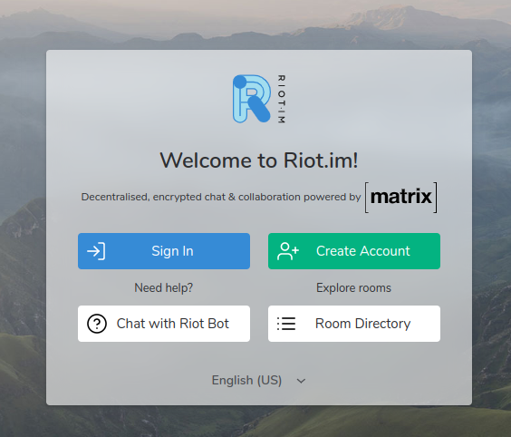
We will use the default web interface https://riot.im/app and request a free matrix.org account.
The Riot.im home
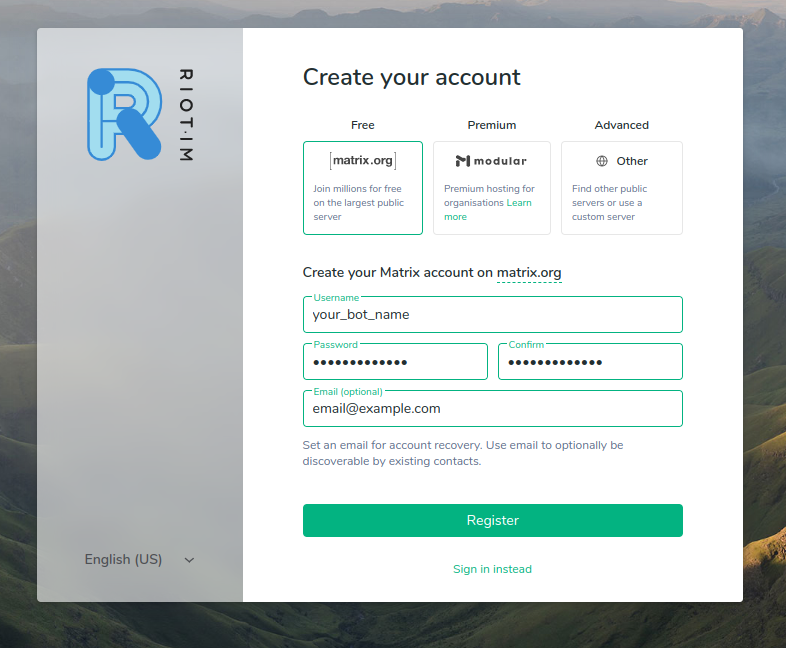
You have to pick a username, for example rook_the_bot, which will provide a matrix identifier/address such as “@rook_the_bot:matrix.org” after creation.
The riot account creation interface
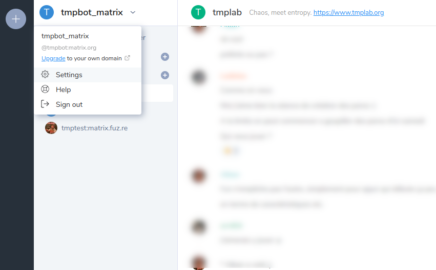
One your mail is validated, log in the web interface and head to the settings page to retrieve the token.
A Riot settings menu link
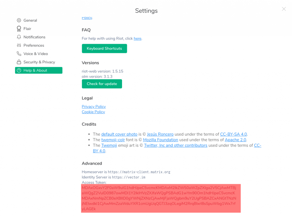
You will find it token at the end of the “Help & About” page: click on the <click to reveal> link, and copy the string that appears.
Riot token finally shows up!
Time to head back to your maubot instance, and click on the Client “⊕” button. Fill the requested informations : the username you created and the access token are mandatory. Validate.
The maubot client menu
And that’s it. You’re ready for the last stage.
Add an instance
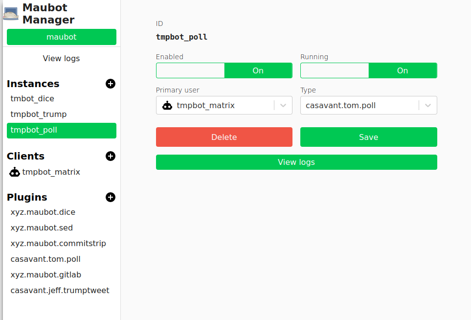
Head your maubot instance and client on the Instances “⊕” button.
The maubot instance menu
Justpick a client and a plugin before validating.
And now you should have your first bot ready! Congratulations!
How to use your bot
Now if everything went well, you should be able to invite your bot in a room, using the matrix handle you created earlier, as in our example rook_the_bot@matrix.org.
Let’s say you created an “Instance” associating the dice “Plugin” to the rook_the_bot “Client” .
Once you invited rook_the_bot to your channel, simply type a !dice command. Your bot should after a while reply to you.
Each plugin has its own commands, and you can attach multiple plugins to a single client. But all commands use the front ! mark.
That’s it, have fun. And for questions or anything else… see you on matrix!
Le /tmp/lab est une association loi 1901. Afin de fonctionner plus conformément à sa vision de l’organisation interne d’un hackerspace, elle a procédé en 2019 à une modification de ses statuts.
Ces statuts sont accompagnés d’un Règlement Intérieur ; les deux documents sont disponibles sur ce dépôt git. Ceci a deux buts. D’abord suivre les modifications qui adviendraient. Mais aussi servir d’inspiration pour d’autres ; les statuts d’associations comme Lautre.net ou Lorraine Data Network nous ont été une source d’inspiration essentielle, ce n’est que justice de publier les nôtres.
Statuts + Règlement Intérieur : quel intérêt ?
Les statuts sont généraux et relativement immuables. Ils définissent les règles fondamentales de l’association et en particulier son mode d’organisation dit autogéré, sans le triumvirat habituel (secrétaire / trésorière.er / présidente).
Ils délèguent au Règlement Intérieur les modalités d’application de certaines règles. Ainsi, les statuts précisent que l’Assemblée Générale est réunie de manière permanente via la mailing list de l’association ; c’est le règlement intérieur qui définit les délais impartis à la prise de décision sur cette mailing list.
De plus le Règlement Intérieur définit le cadre de la vie collective au sein du hackerspace.
Retour d’expérience sur le fonctionnement
Nous sommes satisfaits de cette solution et de la liberté qu’elle nous offre. Elle place au coeur de l’activité les échanges sur la Mailing List et permet des prises de décision assez rapides.
Le délai avant qu’une décision soit prise pose encore question : est-ce que 7 jours sont trop peu ? un délai 15 jours trop long ? Il est également prévu d’écrire un script qui automatise l’enregistrement des propositions et au terme du délai imparti notifie sur la mailing-list leurs validations. Mais le rythme actuel n’a pas encore nécessité cet outil.
Au terme d’une année, alors que se profile notre Assemblée Générale Ordinaire, il est satisfaisant de se dire que pour l’Ordre du Jour, il suffira de synthétiser les décisions proposées et votées sur notre mailing-list interne !
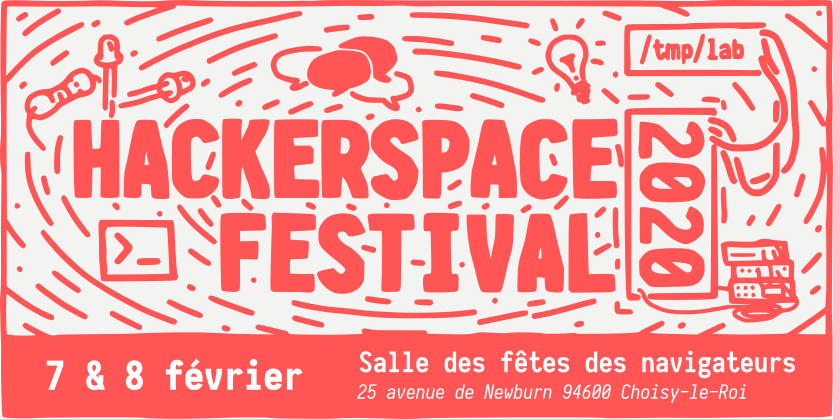
Organizing collective events is an important moment in the life of a hackerspace. The /tmp/lab was happy to organize a new edition of HSF on the 7th and 8th of February 2020.
A number of people helped us for HSF2020, we would like to thank all of them in no particular order or exhaustivity : Choisy’s city employees, participant hackers, lab’s members, and of course everyone who came.
Speaking of audience, the success of such an event is often measured by the attendance. Well, we chose to move that target.
We decided early to respect a few principles for this edition. These were presented as No stress, Auto organize, Party Time, Less conferences, No budget.
Turns out the event was generally perceived as welcoming and had few material constraints. The suburbian city of Choisy-le-Roi, which hosts the /tmp/lab, lent us for free a nice and well equiped room with an additional place for storing and restoring staff. We had no sponsor and required no entrance fee, other than a small “tip box.”
It was globally perceived as a success.
We had a good amount of visitors who appreciated the contact quality, having the time to speak with exhibitors and speakers who themselves liked the relaxed atmosphere and the self-organisation.
Of course, not everything worked perfectly. For example some exhibitors expected we would have more attendance. Some people felt the Friday+Saturday format was a bit short and would have liked a Sunday prolongation. Food for Thought.
So, What About Next Time ?
This event wasn’t too much effort —you know what we mean if you’ve organized such events yourself— nor too costly, which means it can be done more often. But it’s even better if we collectively organize these events in different places every time and this leads us to an interesting effort we associated the HSF2020 event with: the interhackerspaces cooperation.
People from ~10 hackerspaces came and we had a nice panel about how we could do more together. A few notes and links can be found on this pad.
Amongst other proposals, we presented this PDF document which explains what hackerspaces are, how they work and some of their today’s goals.





![Kubernetes Security tech session [Upcoming]](https://www.tmplab.org/wp-content/uploads/2020/07/k8s-matrix.png)